Stent delivering system and back releasing assembly thereof

A delivery system and post-release technology, applied in stents and other directions, can solve the problems of large release resistance, large friction area, and displacement of stent-graft stent-grafts, and achieve the effects of increasing reliability, small contact area, and improving accuracy

Inactive Publication Date: 2016-09-21
SHANGHAI MICROPORT ENDOVASCULAR MEDTECH (GRP) CO LTD
View PDF7 Cites 12 Cited by
  • Summary
  • Abstract
  • Description
  • Claims
  • Application Information

AI Technical Summary

Problems solved by technology

[0005] 1. The stent-graft without a post-release system, that is, the stent-graft is released directly, and the stent-graft is released by the retraction of the outer tube. The disadvantage is that the released stent-graft will migrate under the action of blood flow and impact. resulting in inaccurate final stent graft position;
[0006] 2. For the banded stent graft, the banded stent graft is also released by withdrawing the outer tube, and the binding wire is untied by controlling the twitch of the guide wire to release the stent graft. The disadvantage is that the stent graft may be shortened.

Method used


Image

  • Stent delivering system and back releasing assembly thereof
  • Stent delivering system and back releasing assembly thereof

Examples


Embodiment Construction

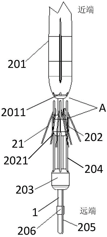
[0027] The stent delivery system and the subsequent release assembly proposed by the present invention will be further described in detail below with reference to the accompanying drawings and specific embodiments. Advantages and features of the present invention will be apparent from the following description and claims. It should be noted that the drawings are all in a very simplified form and use imprecise ratios, which are only used to facilitate and clearly assist the purpose of illustrating the embodiments of the present invention. For ease of description, the proximal end described in the embodiments of the present invention refers to the forward end of the stent delivery system, that is, the end away from the operator, and the distal end refers to the end close to the operator.

[0028] The core idea of ​​the present invention is to provide a rear release assembly of a stent delivery system, which realizes the restraint of the proximal end of the stent through several ...


PUM


Abstract

The inversion provides a stent delivering system and a back releasing assembly thereof. Constraint of a near end of a stent is achieved through a plurality of back releasing rods; during installation, the near end of the stent is hanged on all the back releasing rods, the back releasing rods are pushed into fixing holes of a conical head through a back releasing back end so as to constrain the near end of the stent; during releasing of the near end of the stent, a back releasing guide wire is pulled to drive the back releasing back end and the back releasing rods fixed on the back releasing back end to move axially, and then the back releasing rods depart from the fixing holes of the conical head, the near end of the stent is disengaged with the back releasing rods, and the near end of the stent is released. The back releasing assembly can effectively constrain the near end of the stent through a back releasing fixing member of the back releasing assembly; the reliability of axial movement of the back releasing rods can be improved; resistance is less during releasing due to small contact areas between the back releasing rods and the fixing holes; and the accuracy of the whole releasing process can be improved.

Description

technical field [0001] The invention relates to the field of medical operation equipment design, in particular to a stent delivery system and a post-release assembly. Background technique [0002] A stent graft is an implantable device consisting of a tubular surgical graft sheath and a self-expanding frame. The covered stent is placed in the blood vessel, which can block the aneurysm and rebuild the blood flow path, so that the hemodynamic pressure cannot reach the vascular lesion. [0003] When the stent graft is released in the segment of the blood vessel that needs to be repaired, it needs the cooperation of the delivery system. During the implantation of the covered stent, due to the impact of the blood flow, the covered stent often shifts and folds, so it is particularly critical to accurately locate the position of the covered stent. Therefore, during the operation, it is necessary to release the stent body of the stent-graft first, restrain the bare stent section a...

Claims


Application Information

Patent Timeline
IPC IPC(8): A61F2/962
CPCA61F2/962A61F2002/9534
Inventor 李中华朱清彭大冬刘梦钦黄定国苗铮华
Owner SHANGHAI MICROPORT ENDOVASCULAR MEDTECH (GRP) CO LTD
Why Eureka
Try Eureka