Fixture for fine-milling top surface and fine-boring cylinder bore of thin-walled cylinder block

A thin-walled cylinder, fine milling technology, applied in the direction of clamping, manufacturing tools, other manufacturing equipment/tools, etc., can solve problems affecting the machining accuracy of cylinder bores, difficulty in mounting pressure plates and clamping, etc., to reduce operating strength and improve Machining accuracy, the effect of avoiding cumulative errors

Active Publication Date: 2017-11-21
GUANGXI YUCHAI MASCH CO LTD
View PDF7 Cites 0 Cited by
  • Summary
  • Abstract
  • Description
  • Claims
  • Application Information

AI Technical Summary

Problems solved by technology

[0007] The thrust gear of the cylinder block and the spindle hole at the rear end, two points on the side close to the top surface, and the thrust surface are positioned. When clamping the other side of the cylinder block, the fixture must consider the clamping problem of the thin-walled cylinder block in the direction of the thrust surface positioning. Because the large deformation affects the machining accuracy of the cylinder bore, the end face of the cylinder block cannot be clamped, but the thrust gear of the cylinder block should be clamped, but it is difficult to install the pressure plate and clamp
[0008] The thrust gear of the cylinder block and the main shaft hole at the rear end, the two points on the side close to the top surface, and the thrust surface are positioned. When clamping the other side of the cylinder block, the clamp cannot directly clamp the side of the cylinder block, because the side is thin, and the clamping deformation will affect the cylinder. Hole machining accuracy

Method used


Image

  • Fixture for fine-milling top surface and fine-boring cylinder bore of thin-walled cylinder block
  • Fixture for fine-milling top surface and fine-boring cylinder bore of thin-walled cylinder block
  • Fixture for fine-milling top surface and fine-boring cylinder bore of thin-walled cylinder block

Examples


Embodiment Construction

[0031] The specific embodiments of the present invention will be described in detail below in conjunction with the accompanying drawings, but it should be understood that the protection scope of the present invention is not limited by the specific embodiments.

[0032] Unless expressly stated otherwise, throughout the specification and claims, the term "comprise" or variations thereof such as "includes" or "includes" and the like will be understood to include the stated elements or constituents, and not Other elements or other components are not excluded.

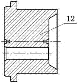
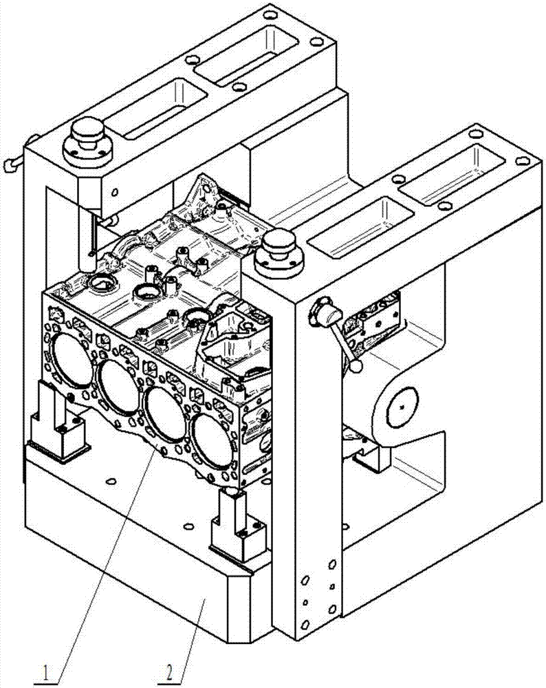
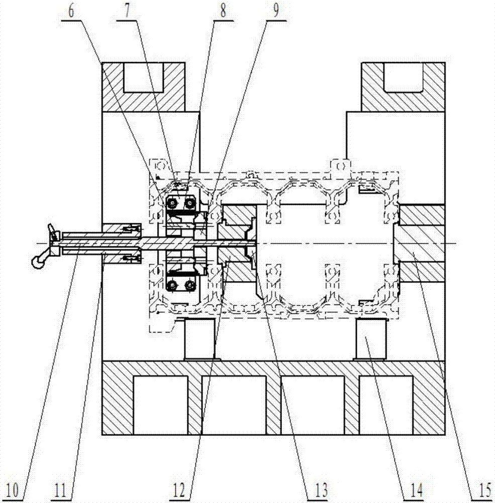
[0033] like Figure 1 to Figure 4 As shown, according to the specific embodiment of the present invention, the jig for fine-milling and fine-boring the top surface of the thin-walled cylinder block is a frame-shaped structure, and the specific structure includes: base 2, left support arm 3, right support arm 5, pressure plate assembly, stop Push gear locating pin 12, rear end locating pin 15 and clasping rod assembly.

[...


PUM


Abstract

The invention discloses a clamp for finely milling a top surface and finely boring a cylinder hole on a thin-walled cylinder block. The clamp comprises a base, a left supporting arm, a right supporting arm, a pressing plate assembly and a holding rod assembly, wherein the base is L-shaped; a thrust gear locating pin boss and a rear end locating pin boss are relatively arranged in the middle of a vertical plane of the base; a thrust gear locating pin and a rear end locating pin are arranged on the vertical plane of the base; the pressing plate assembly comprises a supporting seat, a spring, a pressing plate, a clamping screw, a screw bushing and a supporting block; the clamping screw is in a stepped shaft structure; pressing plate steps are arranged in the middle of the clamping screw; the supporting seat is fixed at the outer side of the thrust gear locating pin boss; the pressing plate is pulled on the supporting seat through the spring; the supporting block is fixed at the right side of the thrust gear locating pin boss; an eccentric screw hole is formed in the middle of the supporting block; and the holding rod assembly comprises a holding rod, a holding rod bushing, a conical head locking screw and a handle. According to the clamp, accumulative errors of reference change are avoided, a top surface and a cylinder hole with high precision requirements are directly processed, and the processing precision can be improved.

Description

technical field [0001] The invention relates to the field of engines, in particular to a jig for fine-milling and fine-boring cylinder holes on the top surface of a thin-walled cylinder body. Background technique [0002] The machining accuracy and mutual positional relationship of the top surface of the engine cylinder block, cylinder bore, and main shaft hole have an important impact on the engine performance. Generally, the design drawings of the cylinder block have a great influence on the flatness of the top surface, the distance from the top surface to the front and rear end main shaft holes, the diameter of the cylinder bore and the circle. There are very high requirements. During machining, the fixture must consider how to locate and clamp the cylinder block to meet the design requirements, and the thin-walled cylinder block must also consider how to avoid deformation during clamping. [0003] Most of the cylinder block adopts the positioning method of two pins on o...

Claims


Application Information

Patent Timeline
Patent Type & Authority Patents(China)
IPC IPC(8): B23Q3/06B23P23/02
CPCB23P23/02B23Q3/065
Inventor 廖继光
Owner GUANGXI YUCHAI MASCH CO LTD
Why Eureka
Try Eureka