Plate machining unit

A sheet metal processing and unit technology, applied in the field of sheet metal processing, can solve the problems of large labor consumption and achieve the effect of convenient disassembly and assembly and simple structure

Inactive Publication Date: 2016-09-21
SUZHOU TIANYUAN FURNITURE CO LTD
View PDF5 Cites 6 Cited by
  • Summary
  • Abstract
  • Description
  • Claims
  • Application Information

AI Technical Summary

Problems solved by technology

[0006] The purpose of the present invention is to solve the defect of large labor consumption in the plate processing process in the prior art, and provide a plate processing unit to solve the above problems

Method used


Image

  • Plate machining unit
  • Plate machining unit
  • Plate machining unit

Examples


Embodiment 1

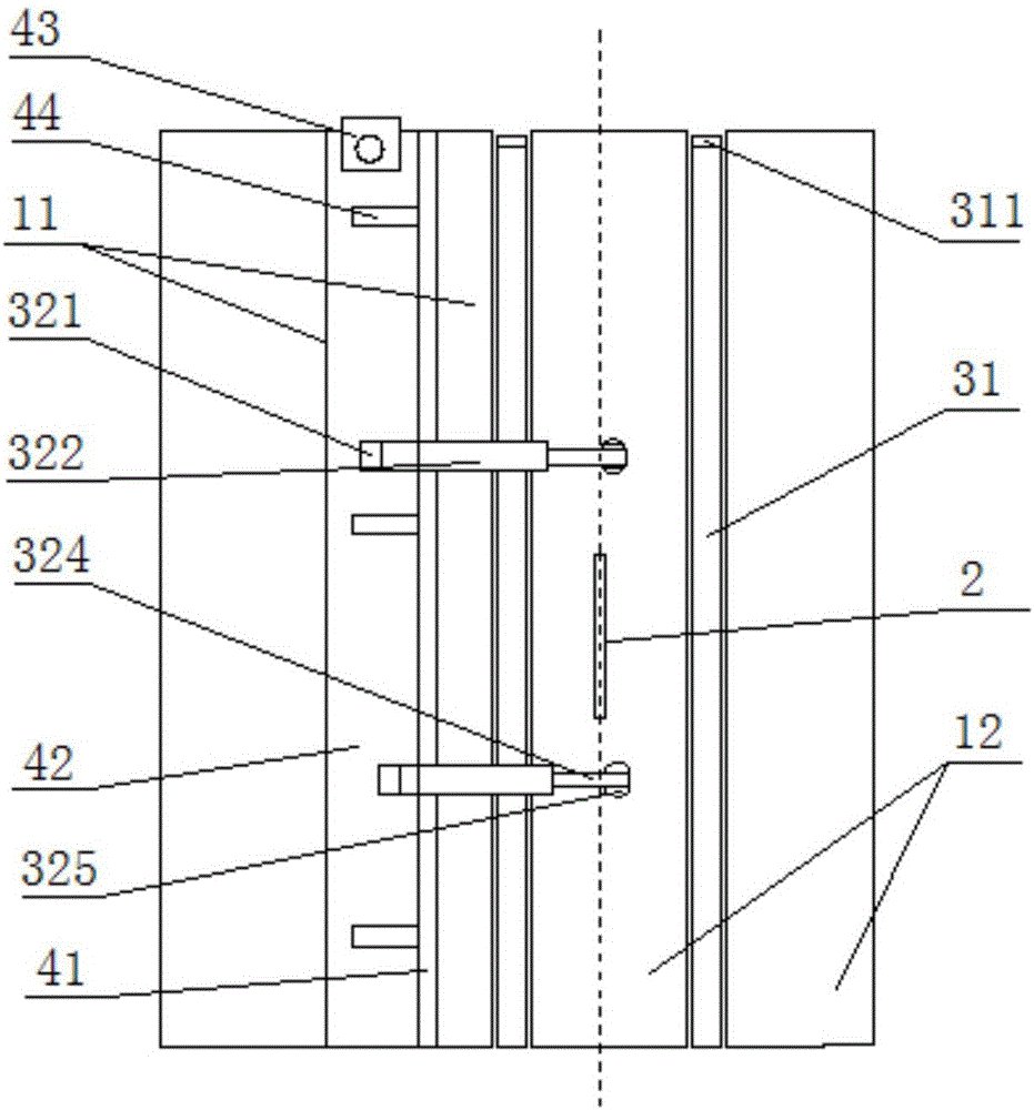
[0061] 2 first transfer parts 31 are all fixed on the right workbench 12, as figure 2 shown.

Embodiment 2

[0063] Or one of the first transfer parts 31 is fixed on the left workbench 11, and the other first transfer part 31 is fixed on the right workbench 12, as image 3 shown.

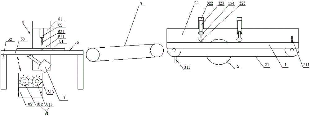
[0064] The first conveying part 31 provided by the present invention is a conveyor belt; the moving path of the conveyor belt is parallel to the grinding wheel saw 2; the upper surface of the conveyor belt is lower than or equal to the upper surface of the workbench 1. It is convenient to ensure the flatness of the board.

[0065] Of course, in order to realize the pushing of the plates, at least the push plate is fixed on the incoming material end of the conveyor belt, that is, the above-mentioned pushing part 311; push plates are fixed at both ends of the conveyor belt to realize the purpose of continuous processing.

[0066] Such as Figure 6 Shown, drilling machine comprises workbench two 5 and drilling mechanism 6, and drilling mechanism 6 comprises power part 61 and drilling part 62; Power part 61 ...


PUM


Abstract

The invention provides a plate machining unit. The plate machining unit comprises a cutter and a drilling machine connected through a second conveying part. The cutter includes a pushing mechanism and a movable limiting mechanism. A worktable 1 is sawed as a left worktable and a right worktable by a grinding wheel saw; the pushing mechanism includes at least one first conveying part; a pushing part is at least arranged at an incoming end of the first conveying part; plates are put on the worktable 1, and are forwards pushed in the direction of the grinding wheel saw through matching between the pushing part and the first conveying part; the grinding wheel saw is positioned between two ends of the first conveying part; and the pushing mechanism further includes at least one plate pressing device. The plates cut by the cutter are conveyed to the drilling machine through a second transfer part; the process is smooth; too many labors are not needed; and the working efficiency is high. The plate machining unit can achieve the purposes of automatically pushing the plates and machining the plates with different sizes through the pushing mechanism and the movable limiting mechanism.

Description

technical field [0001] The invention relates to the technical field of plate processing, in particular to a plate processing unit. Background technique [0002] Wood is widely used in decoration and furniture because of its easy processing and good performance. [0003] In order to process furniture of a specific size and shape, it is necessary to process various shapes and open holes on the board. In the unit in the prior art, when cutting the board, the usual cutting machine uses manual pushing of the board. During the cutting process, because the staff pushes the board closer to the cutting point, the dust raised by the cutting is harmful to the health of the personnel, and the pushing The process is time-consuming and labor-intensive. The next plate can only be placed after one plate is cut. The processing continuity is poor, resulting in low efficiency. Moreover, in order to facilitate cutting, a limit plate is generally fixed on the workbench 1. The immovability of t...

Claims


Application Information

Patent Timeline
Patent Type & Authority Applications(China)
IPC IPC(8): B24B27/06B24B55/06B27C3/02B27G3/00
CPCB24B27/06B24B55/06B27C3/02B27G3/00
Inventor 祝业超
Owner SUZHOU TIANYUAN FURNITURE CO LTD
Why Eureka
Try Eureka