Pressure control method for brake cylinder of magnetically levitated train

A technology of brake cylinder pressure and maglev train, which is applied to brakes, brake components, pneumatic brakes, etc., can solve the problems of slow pressure boost of the brake cylinder, longer braking distance, and longer idle time of maglev trains. Achieve precise control, improve steady-state performance, and shorten braking distance

Inactive Publication Date: 2016-09-21
CRRC QINGDAO SIFANG ROLLING STOCK RES INST
View PDF3 Cites 13 Cited by
  • Summary
  • Abstract
  • Description
  • Claims
  • Application Information

AI Technical Summary

Problems solved by technology

If the brake cylinder pressure control method of the urban rail train is still followed, the brake cylinder of the maglev train will be boosted slowly and the idling time will be prolonged, resulting in longer braking distance and lower safety.

Method used


Image

  • Pressure control method for brake cylinder of magnetically levitated train
  • Pressure control method for brake cylinder of magnetically levitated train
  • Pressure control method for brake cylinder of magnetically levitated train

Examples


Embodiment Construction

[0034] Specific embodiments of the present invention will be further described below in conjunction with the accompanying drawings.

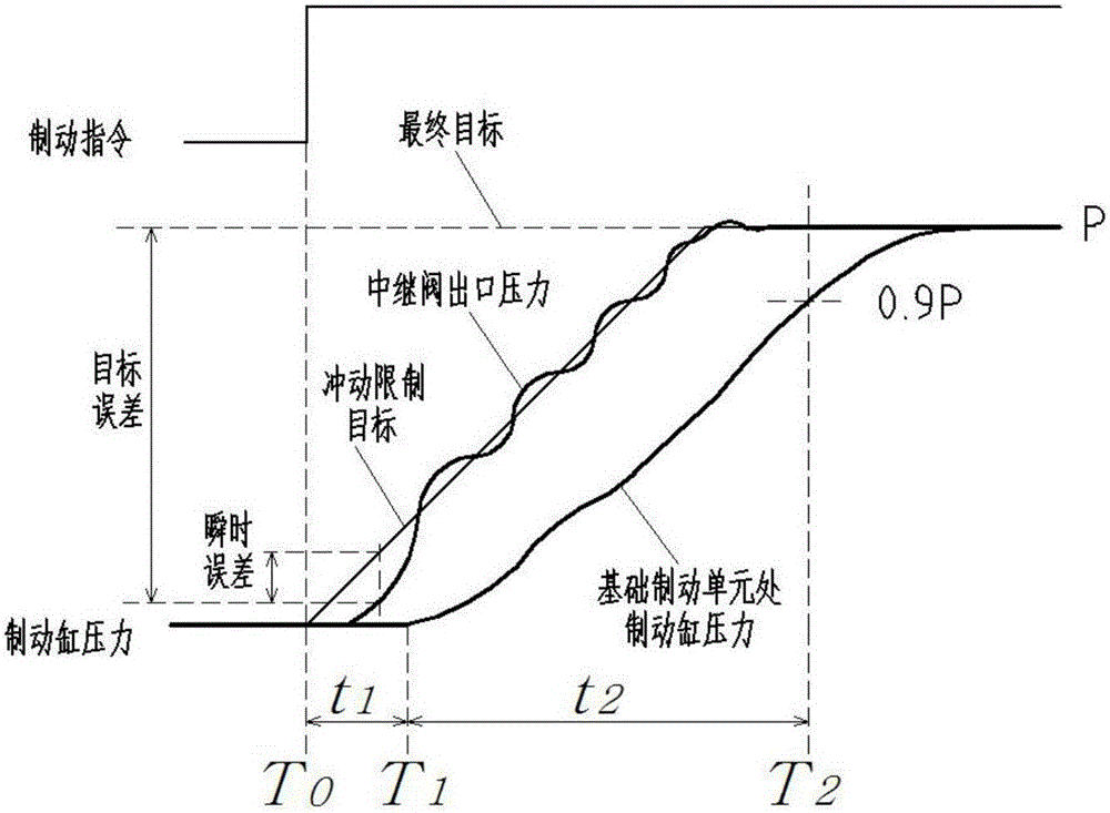
[0035] The brake response time has a great relationship with the mechanical characteristics of the brake system, the volume of the brake cylinder and the length of the pipeline, and also has a great relationship with the control method of the pressure of the brake cylinder. figure 2 is the schematic diagram of brake cylinder pressure and response time, from T 0 Time to issue a braking command to T 1 The moment the brake cylinder pressure starts to rise, during this time t 1 is the idle time, from T 1 From the moment when the pressure of the brake cylinder rises to 90% (0.9P) of the maximum pressure, the time t 2 is the boost time. t 1 +t 2 is the braking response time, so if you want to reduce the braking response time, you can reduce the t 1 and t 2 way to achieve.

[0036] Due to the large average braking deceleration requirements of...


PUM


Abstract

A pressure control method for a brake cylinder of a magnetically levitated train comprises the steps that the error between an actual value of the brake cylinder pressure and a final target value of the brake cylinder is worked out and recorded as a target error; the error between the actual value of the brake cylinder pressure and a target value of the impulse limit of the brake cylinder is worked out and recorded as a transient error; a first threshold value and a second threshold value are set; when the target error is larger than the first threshold value, an inflating and deflating electromagnetic valve is opened normally; when the target error is larger than the second threshold value but smaller than the first threshold value, the open time of the inflating and deflating electromagnetic valve during one control cycle is adjusted according to the transient error and recorded as a rough adjusted duty ratio; when the target error is smaller than the second threshold value, the open time of the inflating and deflating electromagnetic valve during one control cycle is adjusted according to the transient error and recorded as a fine adjusted duty ratio; and the rough adjusted duty ratio is larger than the fine adjusted duty ratio. The method is conducted based on the target pressure and the impulse limit target, on the premise that the impulse limit target and the target pressure of the brake cylinder are met, more precise control can be achieved, the brake response time is shortened, the brake distance is decreased, and the steady-state performance of the brake cylinder is improved.

Description

technical field [0001] The invention belongs to the technical field of rail transit brake cylinder pressure control, and relates to a brake cylinder control method, in particular to a brake cylinder pressure control method for a maglev train. Background technique [0002] The maglev train is a new type of rail transportation. It uses the electromagnetic force between the electromagnet and the track to suspend the train in the air and guide it to realize the non-mechanical contact between the train and the ground track, and then uses a linear motor to drive the train. It has the advantages of fast speed, stable operation, low noise, and small environmental impact. [0003] The maglev train has functions such as common braking, emergency braking, emergency braking, and holding braking. Among them, the common braking adopts the electro-pneumatic hybrid braking method, which is completed by electric braking and air braking, and electric braking is preferred. When the electric b...

Claims


Application Information

Patent Timeline
Patent Type & Authority Applications(China)
IPC IPC(8): B60T15/42B61H11/06
CPCB60T15/42B61H11/06
Inventor 胡波赵欣卢鸣鹤
Owner CRRC QINGDAO SIFANG ROLLING STOCK RES INST
Why Eureka
Try Eureka