
Storage bin structure

A silo body and wall body technology is applied in the field of storage and storage silo structures to achieve the effects of improving heat dissipation, reasonable structure and preventing heat accumulation

Inactive Publication Date: 2016-09-21
王国良
View PDF0 Cites 2 Cited by
  • Summary
  • Abstract
  • Description
  • Claims
  • Application Information

AI Technical Summary

Problems solved by technology

However, although the current grain and oil storage device can achieve ventilation and a certain degree of cooling and heat dissipation, it is still lacking in avoiding heat accumulation caused by sun exposure and adjusting the form of heat dissipation in different weather.

Method used


Image

  • Storage bin structure
  • Storage bin structure
  • Storage bin structure

Examples


Embodiment Construction

[0021] The present invention will be further described below in conjunction with the accompanying drawings and specific embodiments.

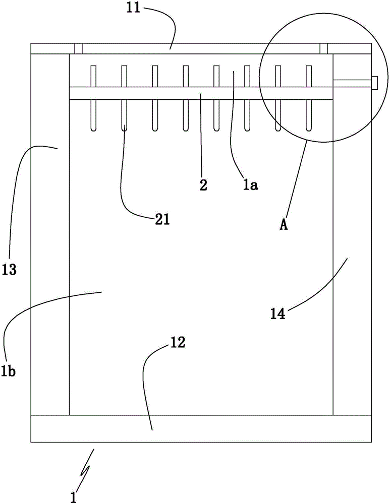
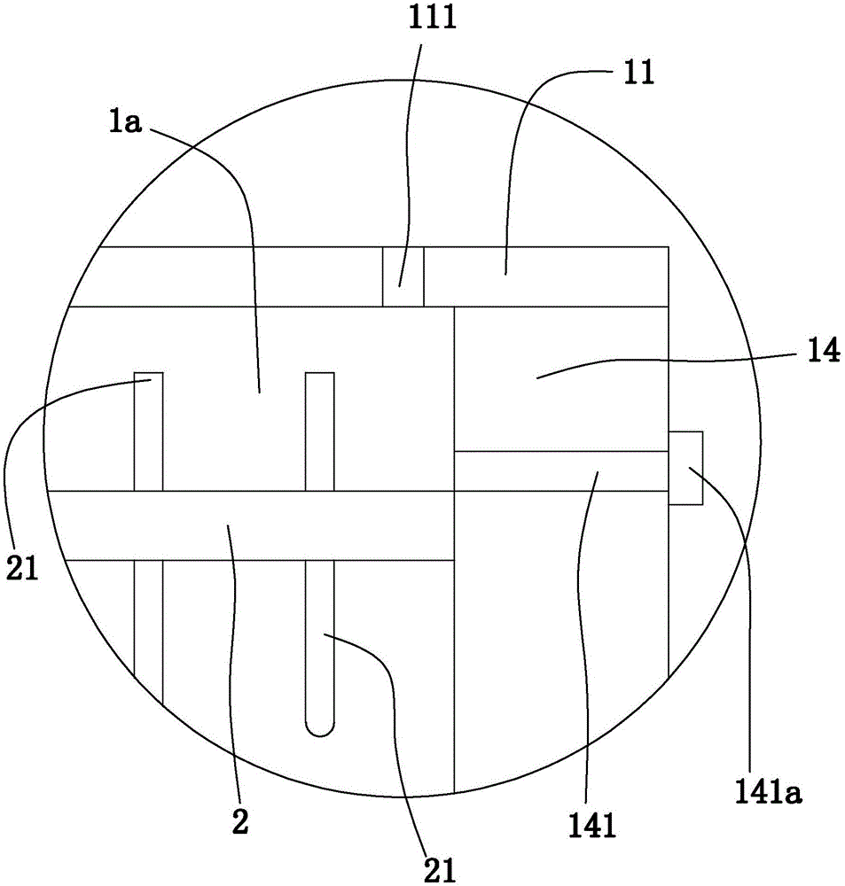
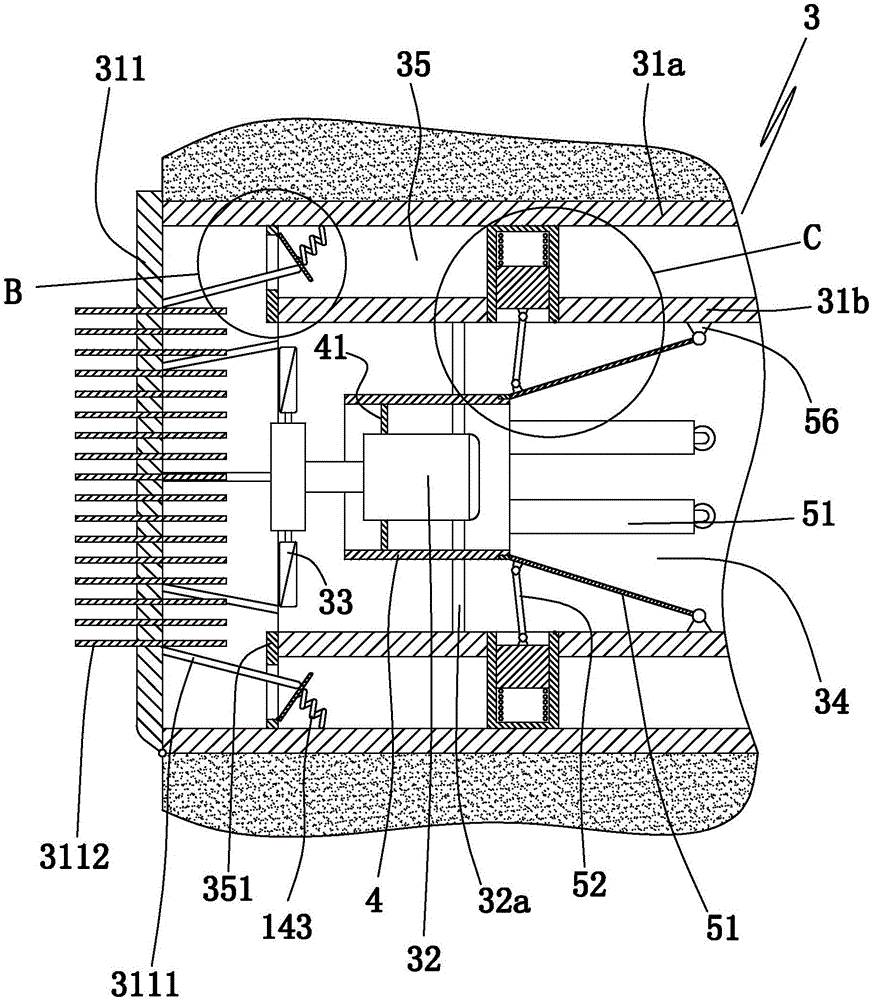
[0022] Such as Figure 1 to Figure 5 In the shown embodiment, a storage bin structure includes a top wall 11, a bottom wall 12, an oppositely arranged front side wall and a rear side wall, an oppositely arranged left side wall 13 and a right side wall 14. The warehouse body 1 is provided with an inner top plate 2 in the warehouse body, the space between the inner roof plate and the top wall in the warehouse body is the top heat insulation cavity 1a, and the space between the inner roof plate and the bottom wall in the warehouse body is the storage chamber 1b, There is a wall air exhaust channel on the left wall, a wall air inlet channel on the right wall, an air inlet channel opening and closing door on the wall air inlet channel, and a number of opening and closing doors on the top wall that communicate with the top heat insulation chamber. T...


PUM


Abstract

The invention discloses a storage bin structure which comprises a bin body. The bin body is formed by a top wall, a bottom wall, a front side wall, a rear side wall, a left side wall and a right side wall jointly, wherein the front side wall and the rear side wall are arranged oppositely; and the left side wall and the right side wall are arranged oppositely. An inner top plate is arranged in the bin body. A top heat-insulating cavity is formed in the space between the inner top plate and the top wall in the bin body. A storage cavity is arranged in the space between the inner top plate and the bottom wall in the bin body. The left side wall is provided with a wall exhaust duct. The right side wall is provided with a wall intake duct, and an intake duct opening and closing door is arranged on the wall intake duct. The top wall is provided with a plurality of rainwater filling openings communicating with the top heat-insulating cavity. The right side wall is provided with a drainage channel communicating with the top heat-insulating cavity. A drainage on-off valve is arranged on the drainage channel. An exhaust fan is arranged in the wall exhaust duct. The storage bin structure has the beneficial effects that the structure is reasonable, heat accumulation caused by exposure in the sun can be prevented effectively, and the cooling capacity can be enhanced and the heat dissipation effect can be improved on rainy days.

Description

technical field [0001] The invention belongs to the technical field of grain and oil storage engineering, and in particular relates to a storage bin structure. Background technique [0002] Present grain and oil storage devices, such as bins, barns, etc., are mainly composed of bins, air ducts arranged on the bin bodies, fans arranged in the air ducts, and the like. The warehouse body is usually set directly on the ground. The main function of the ventilation channel and the fan is to use the fan to make the external low-temperature air pass through the grain pile (material pile) to reduce the temperature inside the warehouse. Grain storage refers to artificially changing the gas composition of the normal atmosphere or adjusting the ratio of the original gas, controlling a certain gas concentration within a certain range, and maintaining it for a certain period of time, so as to achieve the purpose of killing insects, inhibiting mold and delaying the change of grain quality....

Claims


Application Information

Patent Timeline
Patent Type & Authority Applications(China)
IPC IPC(8): B65D88/02B65D90/00B65D90/02
CPCB65D88/02B65D90/00B65D90/02
Inventor 王国良
Owner 王国良
Learn More