Optical glass edge drop material forming device and forming method

A technology of optical glass and forming device, which is applied in the direction of the feeding machine nozzle, etc., can solve the problems of poor optical uniformity of glass, forming streaks, crystallization cannot be effectively controlled, and limited specifications and sizes, so as to improve optical uniformity and stress and control The effect of forming stripes technical difficulties, easy loading and unloading and replacement

Active Publication Date: 2019-02-26
CDGM GLASS LLC
View PDF4 Cites 5 Cited by
  • Summary
  • Abstract
  • Description
  • Claims
  • Application Information

AI Technical Summary

Problems solved by technology

For a series of optical glasses with low viscosity, severe crystallization, and short material properties, it is difficult to form the strip width of more than 180mm, and the thickness is usually less than 30mm. After exceeding the above specifications, forming streaks and crystallization cannot be effectively controlled.
The strip casting method is too simple, the streaks and bubbles in the casting process are difficult to control, the optical uniformity of the glass is poor, and it is difficult to manufacture high-uniformity and high-quality large-diameter optical glass
The technology of the commonly used middle drop molding method is relatively advanced, but this molding method always has an excessive temperature difference between the middle and the outside in the process, resulting in molding streaks and easy crystallization problems. The product can only be divided and selected. The way to remove defects, the size is limited, the yield rate is extremely low

Method used


Image

  • Optical glass edge drop material forming device and forming method
  • Optical glass edge drop material forming device and forming method
  • Optical glass edge drop material forming device and forming method

Examples


Embodiment Construction

[0021] The present invention will be further described below in conjunction with the drawings.

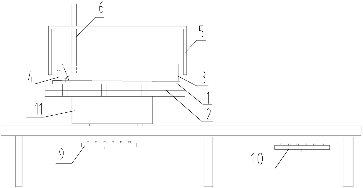
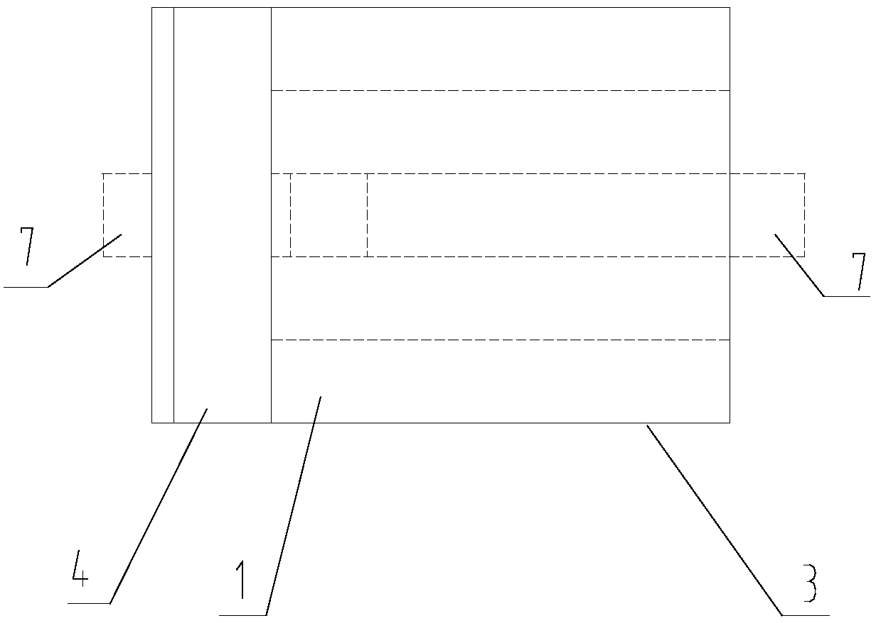
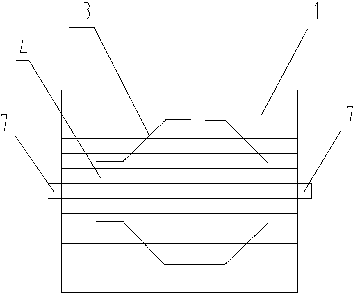
[0022] Such as figure 1 As shown, the large-diameter optical glass drop molding device of the present invention includes a bottom mold 1, a frame 3, a plug 4, a movable pull plate 7, a bracket 2, a rail car 11, a heating system, and a preheating system. The frame 3 and the plug 4 are arranged on the bottom mold 1, and the frame 3 is arranged around the bottom mold 1, the plug 4 is arranged inside the frame 3, and a vertical surface of the plug 4 is in contact with one side of the frame 3, and Use screws to fix. Since the frame 3 has only side surfaces and no bottom surface, the bottom mold 1, the frame 3, and the plug 4 constitute a molding die for optical glass, and the bottom mold 1 and the frame 3 can also be made into an integrated structure. The bottom mold 1 is provided with two embedded movable pull plates 7, and the two pull plates 7 can be pulled out or inserted. When pulled...


PUM


Abstract

The invention provides a molding device and a molding method for optical glass by edge dropwise feeding. The molding device can effectively control the problems of stripes and easy devitrification of the optical glass. The molding device for optical glass by edge dropwise feeding comprises a bottom die, a bracket, a rail trolley, a heating system and a preheating system, wherein the heating system controls the space temperature of molding; the preheating system heats the bottom part of the die; the bracket is arranged on the rail trolley; the bottom die is arranged on the bracket; the molding device also comprises a frame and a plug; and the bottom die, the frame and the plug constitute the molding die of the optical glass. The molding device provided by the invention can well meet the requirements of the process needed by edge molding of heavy-caliber optical glass, has flexible operation, is convenient to assemble, disassemble and replace, effectively improves optical homogeneity and stress of the heavy-caliber optical glass, is applicable to molding of the heavy-caliber optical glass in the forms of crowns, flint, lanthanides, fluorophosphates, etc., and has good effects on solving the problem of molding of low-viscosity and easy-devitrification optical glass of lanthanides, fluorophosphates, etc.

Description

Technical field [0001] The invention relates to a drip molding device and a molding method for large-caliber optical glass, in particular to a molding device and a molding method for large-caliber, low-viscosity, easy-to-crystallize optical glass. Background technique [0002] After the optical glass is melted from powder to qualified glass, in order to keep the glass liquid in a certain shape after solidification, a molding process must be used to gradually solidify the shape when the glass changes from liquid to solid. At present, the molding method of large-diameter optical glass There are mainly the following three types: 1) Strip traction molding method: In the molten state, the optical glass is continuously and naturally formed by a mold or pressed and cut into a certain size of optical glass strip; 2) Casting method: optical glass is in In the molten state, it is poured directly into the forming mold and cooled into the required bulk glass; 3) The middle drip molding metho...

Claims


Application Information

Patent Timeline
Patent Type & Authority Patents(China)
IPC IPC(8): C03B7/08C03B7/096C03B7/094
CPCC03B7/08C03B7/094C03B7/096
Inventor 姚慧贤李天国史国斌谈建龙
Owner CDGM GLASS LLC
Why Eureka
Try Eureka