A centralized waste gas treatment device for in-situ thermal regeneration machines

A centralized processing and regenerating machine technology, applied in lighting and heating equipment, combustion methods, combustion types, etc., can solve problems such as asphalt smoke pollution, environmental pollution, air pollution, etc., and achieve the effect of novel design concepts

Active Publication Date: 2018-04-13
JILIN JIAPENG GRP
View PDF5 Cites 0 Cited by
  • Summary
  • Abstract
  • Description
  • Claims
  • Application Information

AI Technical Summary

Problems solved by technology

[0002] At present, there are existing asphalt pavement hot-in-place regeneration machines at home and abroad, and the heating method is mostly to use fuel oil or gas to directly heat the original road surface. Because the old asphalt pavement contains aged asphalt, after the asphalt is heated to 80 ° C - 200 ° C, it will A large amount of asphalt fume is produced, which is discharged into the air without organization, causing a lot of air pollution, especially in the construction of urban main roads and highways passing through the city, this kind of asphalt fume pollution is particularly serious
At the same time, asphalt fume contains tiny asphalt oil mist particles, which can be fully burned and continue to generate a part of heat. Since this part of resources is directly discharged into the air without organization, it will pollute the environment and cause a waste of energy.

Method used


Image

  • A centralized waste gas treatment device for in-situ thermal regeneration machines
  • A centralized waste gas treatment device for in-situ thermal regeneration machines
  • A centralized waste gas treatment device for in-situ thermal regeneration machines

Examples


Embodiment Construction

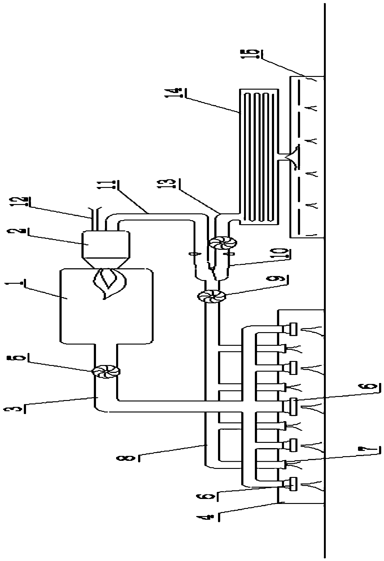
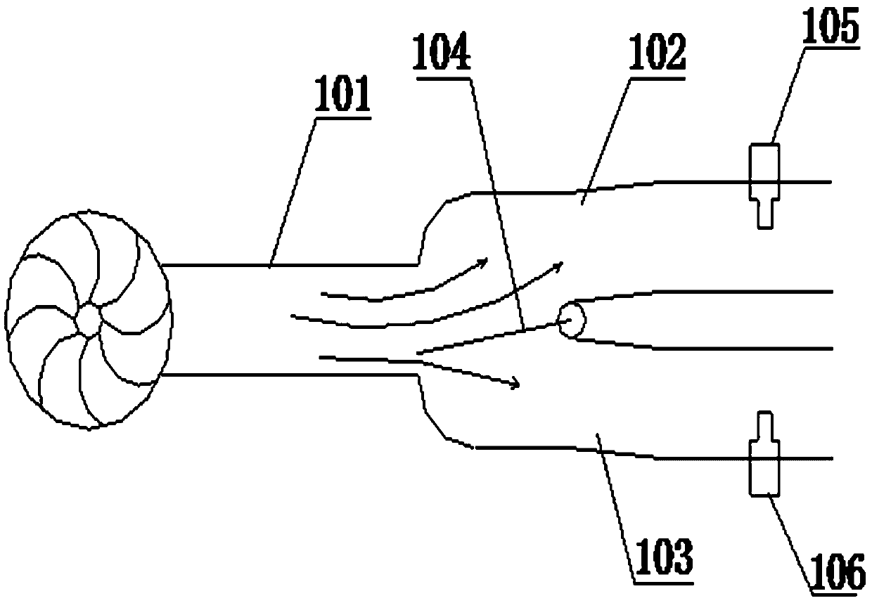
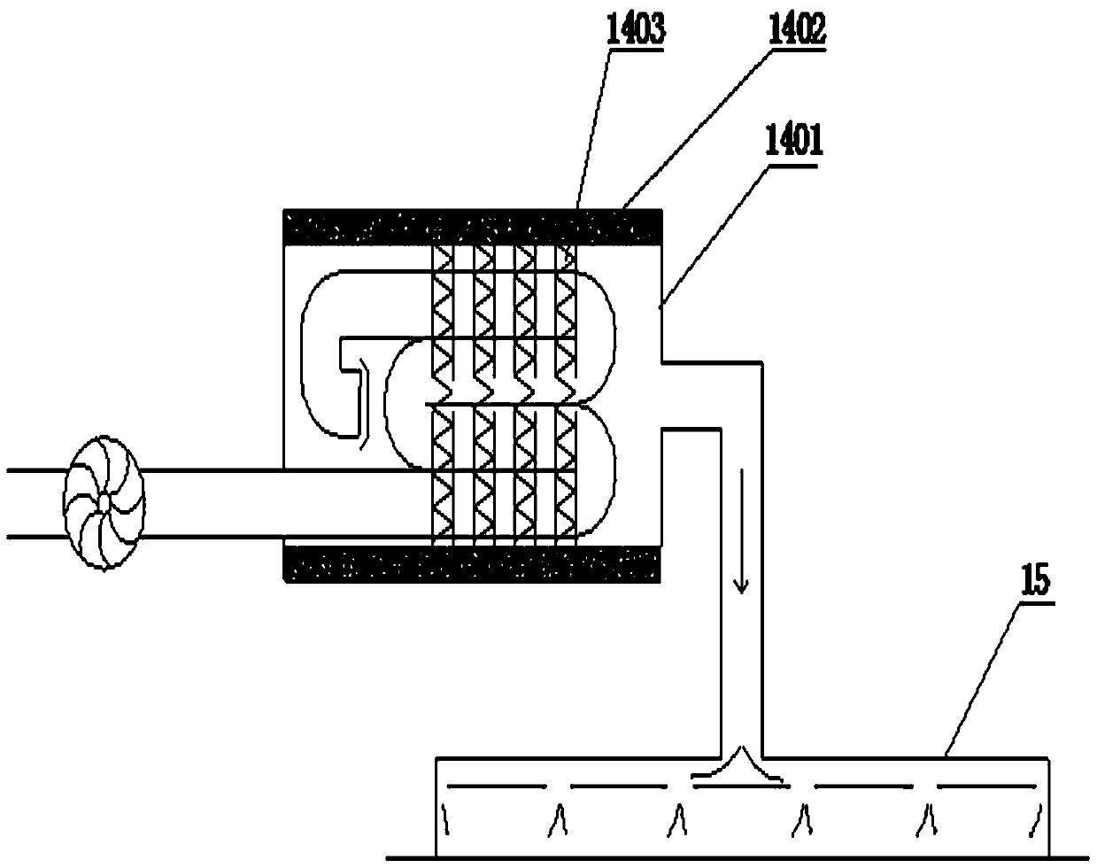
[0022] With reference to the accompanying drawings, a centralized waste gas treatment device for an in-situ thermal regenerator includes an air heater 1, one end of the air heater 1 is provided with a low-oxygen burner 2, and the other end of the air heater 1 is connected to an air outlet. One end of the duct 3 and the other end of the air outlet duct 3 are connected to the first pair of ground heating plates 4 , and a first induced draft fan 5 is arranged on the air outlet duct 3 . An air outlet 6 is arranged on the first pair of ground heating plates 4, and the air outlet 6 communicates with the air outlet duct 3; The air duct 8 is connected, and a second induced draft fan 9 is arranged on the return air duct 8 , and the end of the return air duct 8 is connected with an air volume distributor 10 . The air volume distributor 10 is connected to the low-oxygen burner 2 through the first delivery air channel 11, and the low-oxygen burner 2 is also connected with a fresh air inta...


PUM


Abstract

The invention discloses a waste gas centralized processing device used for a hot in-place recycling machine. The waste gas centralized processing device comprises an air heater. The air heater is provided with a low oxygen burner and connected with an air outlet pipeline. The air outlet pipeline is connected with a first ground heating plate. Air outlet holes and air recycling openings are formed in the first ground heating plate. The air recycling openings communicate with an air return pipeline. The end of the air return pipeline is connected with an air volume distributor. The air volume distributor is connected with the low oxygen burner through a first conveying air duct and connected with an electric heating smoke removing device through a second conveying air duct. An air outlet of the electric heating smoke removing device is connected with a second ground heating plate. According to the waste gas centralized processing device used for the hot in-place recycling machine, poisonous and harmful asphalt flue gas produced by heating of an old asphalt pavement is subjected to centralized collection and centralized processing through the air negative pressure; fuel is fully and circularly utilized; pollution-free hot air is formed after the poisonous and harmful asphalt flue gas is processed; the ground is continuously subjected to heat preservation and heating; energy conservation and environment protection are achieved; atmospheric pollutants are not produced; and the design concept is novel, scientific and environmentally friendly.

Description

technical field [0001] The invention relates to an asphalt pavement construction device, in particular to a waste gas centralized treatment device used on an in-situ thermal regeneration machine. Background technique [0002] At present, there are existing asphalt pavement hot-in-place regeneration machines at home and abroad, and the heating method is mostly to use fuel oil or gas to directly heat the original road surface. Because the old asphalt pavement contains aged asphalt, after the asphalt is heated to 80 ° C - 200 ° C, it will A large amount of asphalt fume is produced, which is discharged into the air without organization, causing a lot of pollution to the air, especially in the construction of urban main roads and highways passing through the city, the pollution of this kind of asphalt fume is particularly serious. At the same time, the asphalt fume contains tiny asphalt oil mist particles, which can be fully burned and continue to generate some heat. Since this p...

Claims


Application Information

Patent Timeline
Patent Type & Authority Patents(China)
IPC IPC(8): E01C19/10F23G7/06F23J15/08
CPCE01C19/1004E01C2019/1081E01C2301/00F23G7/06F23J15/08
Inventor 王志山姜军高金龙
Owner JILIN JIAPENG GRP
Why Eureka
Try Eureka