Girder and multi-cavity steel plate shear wall connecting node and operation method thereof
A steel plate shear wall and connection node technology, applied to walls, building components, buildings, etc., can solve problems such as complex structure, low operational flexibility, and poor adaptability
- Summary
- Abstract
- Description
- Claims
- Application Information
AI Technical Summary
Problems solved by technology
Method used
Image

Examples
Embodiment 1
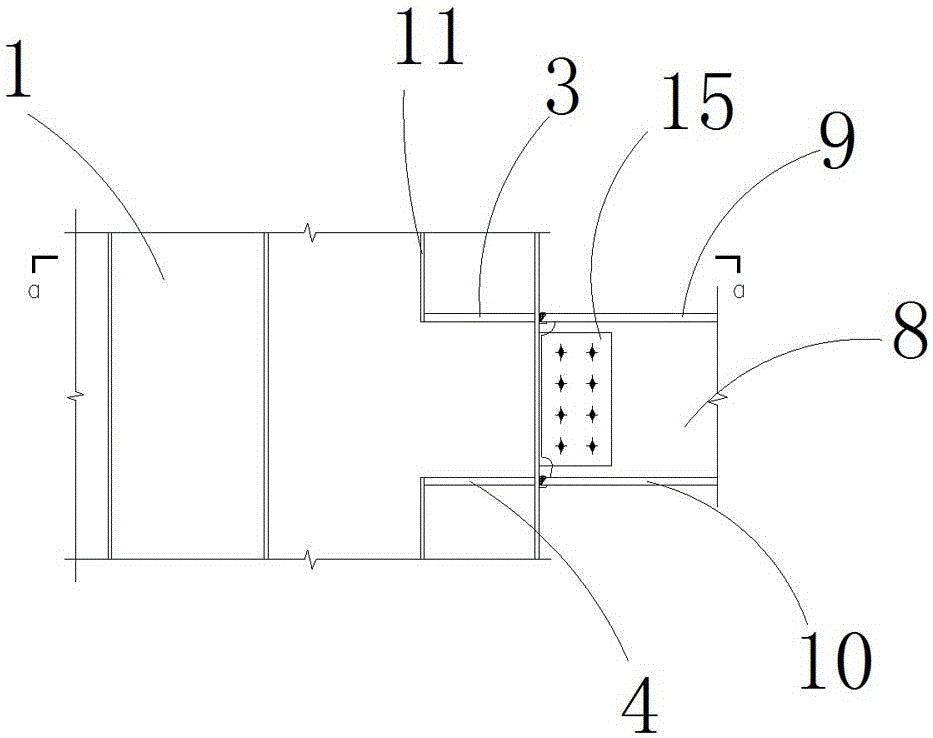
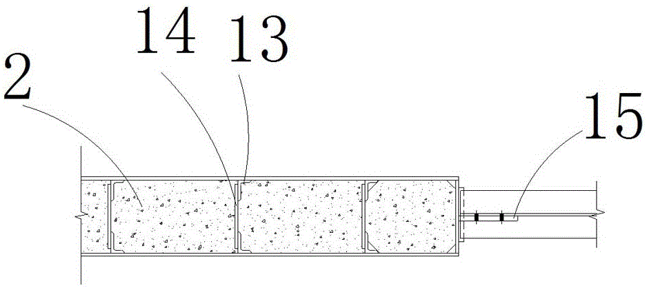
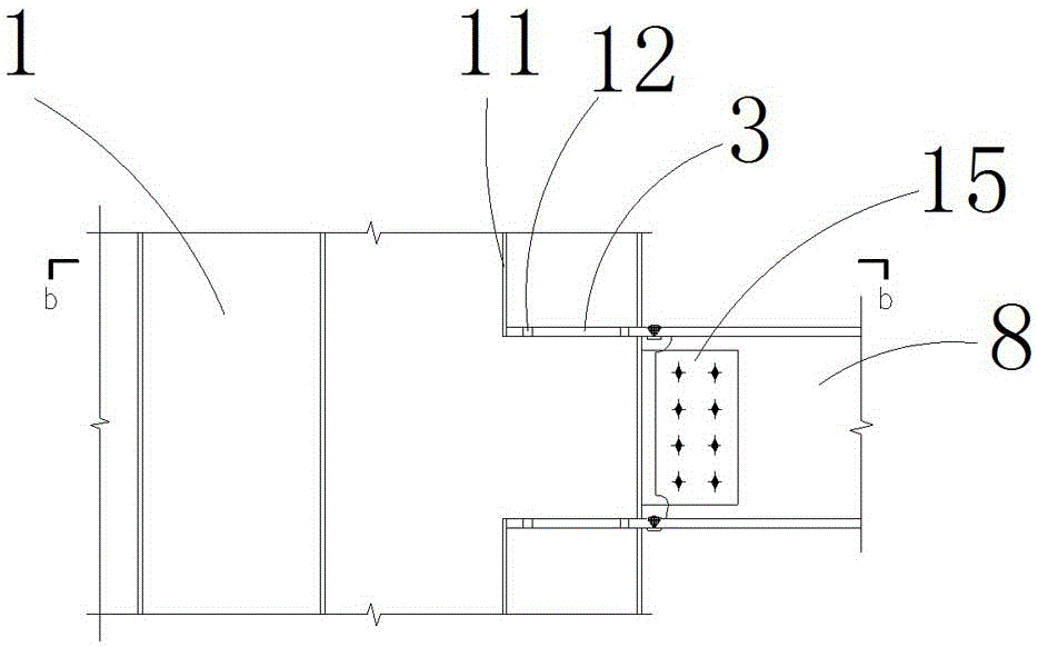
[0054] Embodiment 1: as figure 1 , figure 2 , image 3 with Figure 4 As shown, a connection node between a steel beam and a multi-cavity steel plate shear wall includes a steel plate shear wall 1 and a steel beam assembly, the steel beam assembly is arranged on the outer wall of the steel plate shear wall 1, and the steel plate The end unit of the shear wall 1 is provided with a stiffening assembly, the inner wall of the steel plate shear wall 1 is provided with at least one angle steel assembly, and the steel plate shear wall 1 is provided with concrete 2 .
[0055] The stiffening assembly includes an upper stiffening diaphragm 3 and a lower stiffening diaphragm 4, the upper stiffening diaphragm 3 is arranged at the upper end of the end unit in the steel plate shear wall 1, and the lower stiffening diaphragm 4 is arranged at The lower end of the end unit in steel plate shear wall 1;
[0056]The steel beam assembly includes a web 8, the upper part of the web 8 is provide...
Embodiment 2
[0085] Such as Figure 5 with Image 6 A connection node between a steel beam and a multi-cavity steel plate shear wall is shown, including a steel plate shear wall 1 and a steel beam assembly, the steel beam assembly is arranged on the outer wall of the steel plate shear wall 1, and the steel plate shear The end unit of the force wall 1 is provided with a stiffening assembly, the inner wall of the steel plate shear wall 1 is provided with at least one angle steel assembly, and the steel plate shear wall 1 is provided with concrete 2 .
[0086] The stiffening assembly includes an upper stiffening diaphragm 3 and a lower stiffening diaphragm 4, the upper stiffening diaphragm 3 is arranged at the upper end of the end unit in the steel plate shear wall 1, and the lower stiffening diaphragm 4 is arranged at The lower end of the end unit in steel plate shear wall 1;
[0087] The steel beam assembly includes a web 8, the upper part of the web 8 is provided with an upper flange pla...
Embodiment 3
[0093] Such as Figure 7 with Figure 8 As shown, a connection node between a steel beam and a multi-cavity steel plate shear wall includes a steel plate shear wall 1 and a steel beam assembly, the steel beam assembly is arranged on the outer wall of the steel plate shear wall 1, and the steel plate The end unit of the shear wall 1 is provided with a stiffening assembly, the inner wall of the steel plate shear wall 1 is provided with at least one angle steel assembly, and the steel plate shear wall 1 is provided with concrete 2 .
[0094] The stiffening assembly includes an upper anchor bar 5 and a lower anchor bar 6, and divergent anchor bars 7 are provided above and below the upper anchor bar 5 and above and below the lower anchor bar 6;
[0095] The distribution position of the upper anchor ribs 5 matches the upper flange plate 9 , and the distribution position of the lower anchor ribs 6 matches the lower flange plate 10 .
[0096] The divergent anchor bars 7 are provided...
PUM
 Abstract
Description
Claims
Application Information
 - R&D
- Intellectual Property
- Life Sciences
- Materials
- Tech Scout
- Unparalleled Data Quality
- Higher Quality Content
- 60% Fewer Hallucinations
Browse by: Latest US Patents, China's latest patents, Technical Efficacy Thesaurus, Application Domain, Technology Topic, Popular Technical Reports.
© 2025 PatSnap. All rights reserved.Legal|Privacy policy|Modern Slavery Act Transparency Statement|Sitemap|About US| Contact US: help@patsnap.com