Low-frost device of refrigerating device

A technology for refrigeration appliances and freezer compartments, which is applied to household refrigeration devices, cooling fluid circulation devices, defrosting and other directions, can solve the problems of increased frosting amount, weakened effect of balancing device, waste, etc., and achieves the effect of improving performance

Active Publication Date: 2016-09-21
CHANGHONG MEILING CO LTD
View PDF7 Cites 5 Cited by
  • Summary
  • Abstract
  • Description
  • Claims
  • Application Information

AI Technical Summary

Problems solved by technology

One of them is to connect the external atmosphere with the freezer through the Unicom tube. Using the principle of the float valve, when the freezer is cooling, the pressure in the freezer drops rapidly, the float valve is lifted, and the outside air enters the freezer to balance the air pressure in the freezer. , this method does not process the air so that it directly enters the freezer. If the outside world is under high humidity conditions, more water vapor may enter the freezer, which will increase the amount of frosting; The communication pipe between the membrane and the adsorption material layer connects the freezer with the outside atmosphere, and uses the same principle to balance the air pressure in the freezer. Although this method pre-treats the air, there is a drawback: the adsorption material layer will be saturated after a short period of time. Failure, because it is surrounded by the foam layer and cannot be replaced and regenerated; in addition, when the outside air temperature is low, the pressure difference is small and the driving force is insufficient, the effect of the balance device is obviously weakened, and when the compressor stops, the cold air in the freezer is in vain flow to the outside world, causing waste

Method used


Image

  • Low-frost device of refrigerating device
  • Low-frost device of refrigerating device
  • Low-frost device of refrigerating device

Examples


Embodiment Construction

[0028] The embodiments of the present invention are described in detail below. This embodiment is implemented on the premise of the technical solution of the present invention, and detailed implementation methods and specific operating procedures are provided, but the protection scope of the present invention is not limited to the following implementation example.

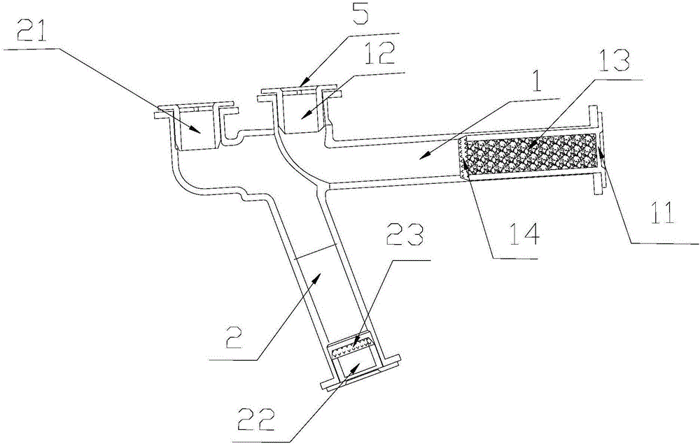
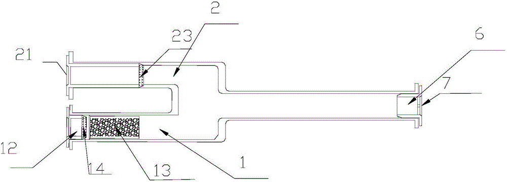
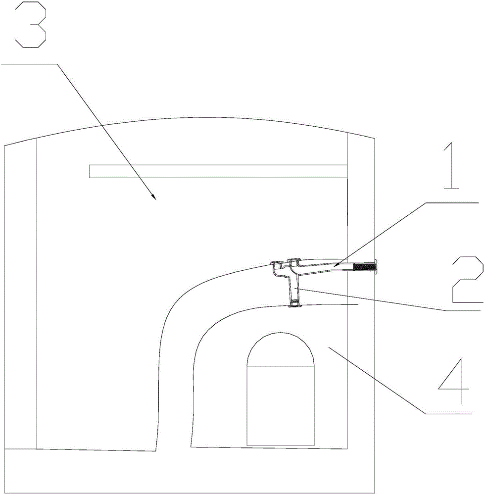
[0029] see figure 1 , figure 2 , this embodiment discloses a low-frost device for a refrigeration appliance, which includes a combined communication pipe, the combined communication pipe includes an air inlet channel 1 and an air outlet channel 2, and the two ends of the air inlet channel 1 are respectively provided with first air inlets 11 and the first air outlet 12, the two ends of the air outlet passage 2 are respectively provided with a second air inlet 21 and a second air outlet 22, and the air inlet passage 1 takes in the air from the first air inlet 11 and the first air outlet 12, Adsorption material lay...


PUM


Abstract

The invention discloses a low-frost device of a refrigerating device. The device comprises a combined communicating pipe; the combined communicating pipe includes an intake channel and an exhaust channel; a first intake port and a first exhaust port are respectively formed in two ends of the intake channel; a second intake port and a second exhaust port are respectively formed in two ends of the exhaust channel; an adsorbing material layer and a first one-way water stop ventilation film are arranged in the intake channel in the intake direction in sequence; the first one-way water stop ventilation film stops water vapor to pass through the surface in the direction of the first intake port to the first exhaust port, and is ventilated in one direction; and a second one-way ventilation infiltration film is arranged in the exhaust channel, and allows the water vapor to pass through the surface in the direction of the second intake port to the second exhaust port, and is ventilated in one direction. The device has the following advantages: the one-way water stop ventilation films in two channels are used for limiting the flowing direction of gas therein as single direction; and the adsorbing material layer is arranged in the intake channel for performing such pretreatment as drying for air entering a freezing chamber.

Description

technical field [0001] The invention relates to the technical field of refrigeration equipment, in particular to a low-frost device for refrigeration equipment. Background technique [0002] As we all know, there is a disadvantage of direct-cooling refrigeration appliances such as direct-cooling refrigerators / freezers, that is, after a period of use, a large amount of frost tends to accumulate on the top of the inner tank and near the door seal, which seriously affects the performance and appearance of the refrigeration appliance. It brings great inconvenience to consumers; in addition, due to the high pressure in the low-temperature compartment and the low air pressure, the door of the appliance is prone to be difficult to open. [0003] For improving this situation, a kind of refrigerating appliance with pressure relief pipe has appeared on the market. One of them is to connect the external atmosphere with the freezer through the Unicom tube. Using the principle of the fl...

Claims


Application Information

Patent Timeline
Patent Type & Authority Applications(China)
IPC IPC(8): F25D21/04F25D17/04F25D21/00
CPCF25D17/042F25D21/00F25D21/04F25D2317/0411F25D2323/0024F25D2321/147F25D21/14F25D2321/146F25D2317/04131
Inventor 程琳涂岩亮张波
Owner CHANGHONG MEILING CO LTD
Why Eureka
Try Eureka