Suction nozzle alignment device and method under visual compensation

A technology of visual compensation and alignment device, which is applied to measurement devices, optical devices, instruments, etc., can solve the problems of being cumbersome, time-consuming, unreliable, and difficult to ensure the position accuracy of cameras and suction nozzles, so as to improve accuracy and reliability. High performance and high precision

Inactive Publication Date: 2016-09-21
HEFEI UNIV
View PDF13 Cites 1 Cited by
  • Summary
  • Abstract
  • Description
  • Claims
  • Application Information

AI Technical Summary

Problems solved by technology

[0003] The existing methods mainly include: 1) Manual visual inspection method, repeated alignment many times, existing defects: cumbersome and time-consuming, unreliable
2) Off-line method, remove the device of camera and suction nozzle and detect it on the three-dimensional scanning coordinate machine, the accuracy is high; the existing defects: the price is expensive, and there will still be relative size changes after the installation is restored; 3) On-line measurement, generally on-site Unable to provide some positioning tools, such as theodolite, especially in the case of small industrial work space, even the tools cannot be placed, the action point of the suction nozzle and the actual position of the camera are often uncertain, and it is difficult to guarantee the position accuracy of the camera and suction nozzle

Method used


Image

  • Suction nozzle alignment device and method under visual compensation
  • Suction nozzle alignment device and method under visual compensation
  • Suction nozzle alignment device and method under visual compensation

Examples


Embodiment Construction

[0022] The following will clearly and completely describe the technical solutions in the embodiments of the present invention with reference to the accompanying drawings in the embodiments of the present invention. Obviously, the described embodiments are only some, not all, embodiments of the present invention. Based on the embodiments of the present invention, all other embodiments obtained by persons of ordinary skill in the art without making creative efforts belong to the protection scope of the present invention.

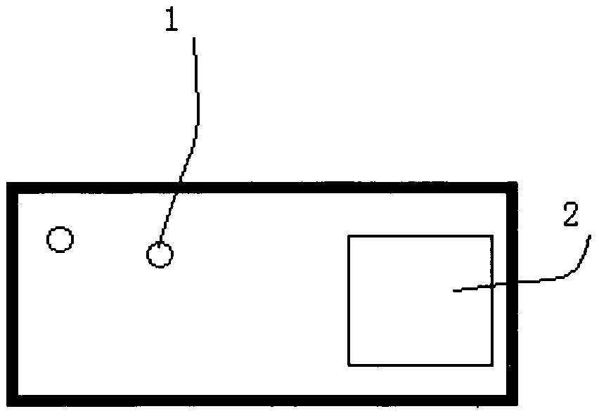
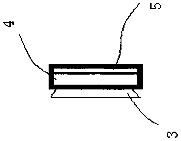
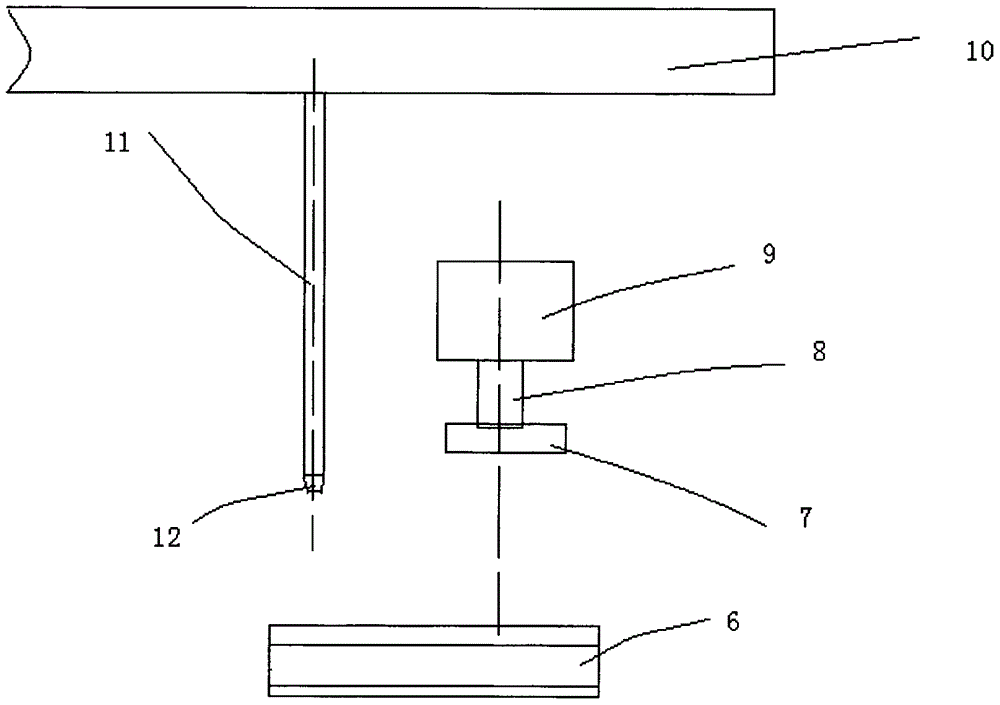
[0023] see Figure 1-3 , the present invention provides a technical solution: a nozzle alignment device under visual compensation, characterized in that it includes a magnetic base 3, a supporting plate 4, a special printing paper 5, an extended calibration plate 6, a light source 7, and a lens 8 , camera 9, displacement mechanism 10, suction rod 11 and suction nozzle 12, it is characterized in that, described supporting plate 4 is arranged on described magnet...


PUM


Abstract

The invention discloses a suction nozzle alignment device and method under visual compensation. The device comprises a magnetic base, a supporting plate, special printing paper, a lengthened scaling board, a light source, a camera, a moving mechanism, a suction rod and a suction nozzle. The supporting plate is arranged on the magnetic base. The special printing paper is arranged on the supporting plate. The moving mechanism is connected with the suction rod. The lower end of the suction rod is provided with the suction nozzle. The camera is arranged below the moving mechanism. The camera is arranged on the lower end of the camera. The light source is arranged on the lower end of the lens. The lengthened scaling board is arranged below the light source. According to the invention, the suction nozzle alignment accuracy and reliability under the visual compensation are effectively improved, the precision is high, the space positions of the camera and the suction nozzle are well ensured, and by using the device and method provided by the invention, the precision of the measured space relative position value between the camera and the suction nozzle under the practical machining state can reach more than 0.01 mm.

Description

technical field [0001] The invention belongs to the technical field of product assembly, and in particular relates to an assembly device and method based on machine vision compensation. Background technique [0002] At present, vision is an effective method to realize the online detection of position error. Usually, the industrial camera fixed on the side of the suction nozzle is used to image the assembly and convert it into an image signal. The suction nozzle picks up the assembly. Parts image; calculate the actual deviation of the nozzle position, output to the servo control system, perform motion compensation, and complete the workpiece processing operation. However, an important issue is how to measure the spatial position of the camera and nozzle online. It is generally impossible to integrate the camera and the suction nozzle, and they all adopt a separate design; this problem is even more obvious for visual inspection tasks with repetitive characteristics and assemb...

Claims


Application Information

Patent Timeline
Patent Type & Authority Applications(China)
IPC IPC(8): G01B11/00
CPCG01B11/00
Inventor 张建中许泽银徐强
Owner HEFEI UNIV
Why Eureka
Try Eureka