Train tractor cooling system

A technology of cooling system and tractor, applied in transformer/inductor cooling, cooling/ventilation/heating transformation, output power conversion device, etc. achieve good results

Inactive Publication Date: 2016-09-21
WUXI JINXIN GRP CO LTD
View PDF8 Cites 2 Cited by
  • Summary
  • Abstract
  • Description
  • Claims
  • Application Information

AI Technical Summary

Problems solved by technology

[0003] The cooling system of the existing train tractor is inefficient and complicated to mainta

Method used


Image

  • Train tractor cooling system

Examples


Embodiment Construction

[0025] The specific implementation of the train tractor cooling system of the present invention will be described in detail below in conjunction with the accompanying drawings.

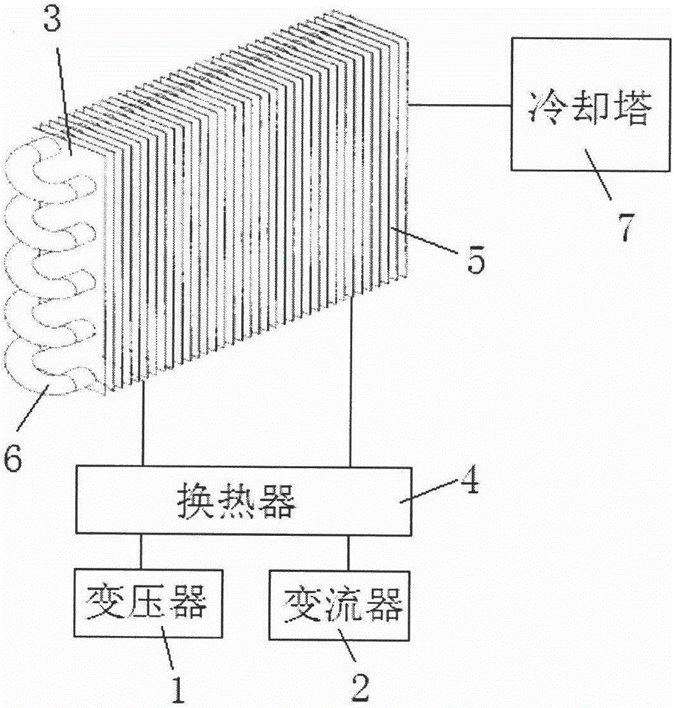
[0026] The train tractor cooling system dissipates heat to the train tractor, so that the tractor drives the train to run at high speed. The tractor includes a transformer 1 and a converter 2. The transformer 1 and the converter 2 are connected to the heat exchanger 4 first, and then connected to the heat sink The radiator 3 and the heat exchanger 4 are priority components. The radiator 3 includes cooling fins 5 and cooling tubes 6 . The cooling tubes 6 are interspersed in the cooling fins 5 .

[0027] The heat dissipation fins 5 are copper sheets, the heat dissipation pipes 6 are copper pipes, the heat dissipation pipes 6 are welded in the heat dissipation fins 5, and the heat dissipation pipes 6 are arranged in a U shape. Cooling water or cooling gas can pass through the cooling pipe 6 . A fan can ...


PUM


Abstract

The invention relates to the technical field of rail train equipment and auxiliary equipment and discloses a train tractor cooling system. A tractor comprises a transformer and a converter. The cooling system comprises a radiator which is connected to the transformer and the converter; the radiator comprises radiating fins and radiating tubes; the radiating tubes are inserted into the radiating fins in a penetrating manner; and the radiating fins are connected with the transformer and the converter. The radiator carries out heat radiation through the fins and the radiating tubes; cooling water is fed into the radiator through a cooling tower; and the tractor is quickly cooled to the optimum working temperature.

Description

technical field [0001] The invention relates to the technical field of rail train equipment and auxiliary equipment, in particular to a train tractor cooling system. Background technique [0002] The high-speed operation of rail trains is completed by tractors. The running speed of existing EMUs or high-speed rail trains is as high as more than 300 kilometers per hour, which requires that the tractors have high-efficiency working capabilities. A large amount of heat needs to be released. If the heat release fails or is not timely, the equipment will be damaged in the slightest, and a major traffic accident will be caused in the severe case. [0003] The cooling system of the existing train tractor is inefficient and complicated to maintain, requiring a lot of manpower and material resources, which affects the efficiency of the train. Contents of the invention [0004] The object of the present invention is to solve the above technical problems and provide a train tractor ...

Claims


Application Information

Patent Timeline
IPC IPC(8): H01F27/08H01F27/16H02M1/00H05K7/20
CPCH01F27/08H01F27/16H02M1/00H05K7/20409H05K7/20863
Inventor 许超谈玉琴张荣
Owner WUXI JINXIN GRP CO LTD
Why Eureka
Try Eureka