Display base board, preparation method thereof, and display apparatus

A display substrate and display unit technology, which is applied in semiconductor/solid-state device manufacturing, instruments, electrical digital data processing, etc., can solve the unfavorable problems of thinner display panels, thicker thickness, and low integration of substrates, so as to improve integration and The effect of added value

Inactive Publication Date: 2016-09-21
BOE TECH GRP CO LTD
View PDF8 Cites 24 Cited by
  • Summary
  • Abstract
  • Description
  • Claims
  • Application Information

AI Technical Summary

Problems solved by technology

[0003] For a display screen with a touch function, it is usually necessary to prepare touch electrodes and sensing electrodes on the substrate on which the display device has been formed (and an insulating layer is also formed between the touch electrodes and the sensing electrodes) , and the integration level of this substrate is also relatively low, and the thickness is relatively thick, which is not conducive to the thinning of the display panel.

Method used


Image

  • Display base board, preparation method thereof, and display apparatus
  • Display base board, preparation method thereof, and display apparatus
  • Display base board, preparation method thereof, and display apparatus

Examples


Embodiment 1

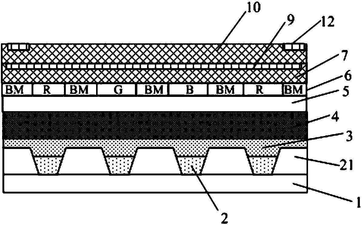
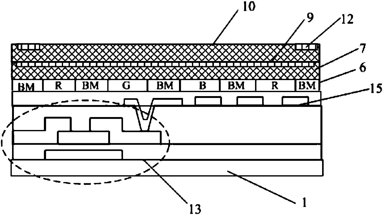
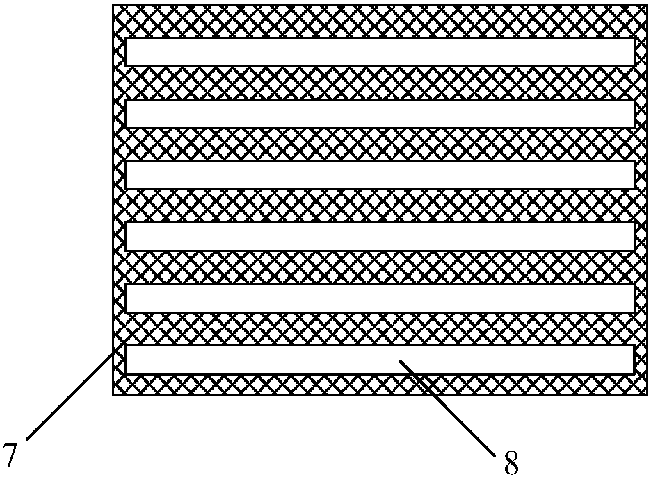
[0060] combine Figure 1-5 As shown, this embodiment provides a display substrate, including a substrate 1, a display unit disposed above the substrate 1, a color filter layer 6 disposed above the display unit, and a first flat layer sequentially disposed above the color filter layer 6 7 and the second flat layer 10; wherein, a plurality of first grooves 8 are arranged on the first flat layer 7; a plurality of second grooves 11 are arranged on the second flat layer 10; a plurality of first grooves Orthographic projections of 8 and multiple second grooves 11 on the substrate 1 are intersected; the first grooves 8 are filled with first wires 9; the second grooves 11 are filled with second wires 12 .

[0061]It can be understood that one of the first wire 9 and the second wire 12 can be used as a touch electrode, and the other can be used as a sensing electrode. That is to say, in the display substrate of this embodiment, the touch electrodes in the touch substrate are integrate...

Embodiment 2

[0076] combine figure 1 , 2 , 6-12 This embodiment provides a method for preparing a display substrate, and the display substrate is the display substrate in Embodiment 1. Described preparation method specifically comprises the following steps:

[0077] Step 1, forming a display unit on the substrate 1 .

[0078] Specifically, such as Figure 7 As shown, if the display substrate is an OLED substrate, Step 1 specifically includes: 1) Sputtering an anode conductive film on the substrate 1, and forming a pattern including the anode layer through a patterning process; 2) forming an anode layer on the substrate 1 1, forming a pattern including the pixel defining layer 21 through a patterning process; 3) on the substrate 1 formed with the pixel defining layer 21, using a vacuum evaporation process to form a light emitting layer in the opening of the pixel defining layer 2121; 4) in On the substrate 1 for forming the luminescent layer, a cathode layer is formed by using a vacuum ...

Embodiment 3

[0090]This embodiment provides a display device, which includes the display substrate described in Embodiment 1, so the display device of this embodiment has high integration and high added value, and can be applied to flexible displays.

[0091] The display device can be any product or component with a display function such as electronic paper, OLED panel, mobile phone, tablet computer, television, monitor, notebook computer, digital photo frame, navigator, etc.


PUM


Abstract

The present invention provides a display base board, a preparation method thereof, and a display apparatus, belonging to the technical field of display. The present invention solves the problem that an existing display base board has a low integration degree and is thick, thereby making a display panel thick and heavy. The display base board includes a base, a display unit, a color membrane layer, a first flat layer and a second flat layer. The display unit is disposed above the base. The color membrane layer is disposed above the display unit. The first flat layer and the second flat layer are sequentially disposed above the color membrane layer. A plurality of first grooves is disposed on the first flat layer. A plurality of second grooves is disposed on the second flat layer. Orthographic projections of the plurality of first grooves and the plurality of second grooves on the base are cross. The first grooves are filled with first leads. The second grooves are filled with second leads.

Description

technical field [0001] The invention belongs to the field of display technology, and in particular relates to a display substrate, a preparation method thereof, and a display device. Background technique [0002] Display screens (touch screens) with touch functions have been used more and more widely. The capacitive touch screen is an important form of the touch screen. There are multiple driving electrodes (Tx) and sensing electrodes (Rx) intersecting each other in the capacitive touch screen. Load the driving signal, and the sensing signal is generated on the sensing electrode; when a touch occurs, the human body or the touch pen approaches the touch area, which affects the capacitance between the two electrodes in the area, and the sensing signal of the corresponding sensing electrode changes, so that it can be determined Touch location. [0003] For a display screen with a touch function, it is usually necessary to prepare touch electrodes and sensing electrodes on the...

Claims


Application Information

Patent Timeline
Patent Type & Authority Applications(China)
IPC IPC(8): H01L27/32H01L51/56G06F3/044
CPCG06F3/044H10K59/40H10K71/00G06F3/0412G06F2203/04103G06F3/0445H10K59/38H10K50/844H10K50/865H10K59/35H10K59/122
Inventor 黄维
Owner BOE TECH GRP CO LTD
Why Eureka
Try Eureka