
Self-adaptive multimode X-ray CT imaging scientific research experimental platform

An experimental platform and CT imaging technology, applied in the fields of application, medical science, radiological diagnostic testing/calibration, etc., can solve the problems of obvious artifacts, unsatisfactory, low resolution, etc., and achieve easy control, small structure, and high precision Effect

Pending Publication Date: 2016-09-28
韩立
View PDF3 Cites 7 Cited by
  • Summary
  • Abstract
  • Description
  • Claims
  • Application Information

AI Technical Summary

Problems solved by technology

However, for imaging organisms used in scientific research, especially medium-sized experimental animals, X-ray CT for medical diagnosis has inherent disadvantages such as low resolution and obvious artifacts due to the use of row detectors and large apertures.
At the same time, the current X-ray CT for biological imaging and human imaging has a fixed aperture, that is, the distance between the X-ray generator and the detector is fixed and cannot be changed, so it cannot meet the needs of various sizes and types of imaging organisms. High-quality low-artifact X-ray CT images required for scientific research

Method used


Image

  • Self-adaptive multimode X-ray CT imaging scientific research experimental platform
  • Self-adaptive multimode X-ray CT imaging scientific research experimental platform
  • Self-adaptive multimode X-ray CT imaging scientific research experimental platform

Examples


Embodiment Construction

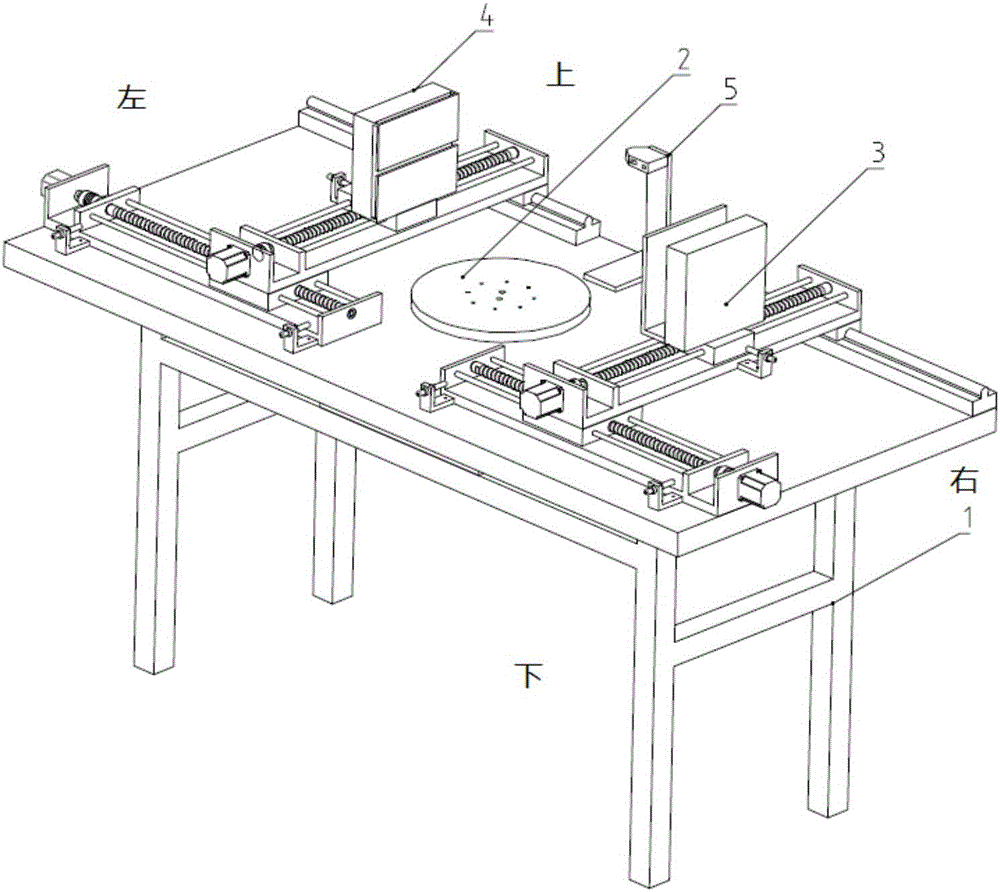
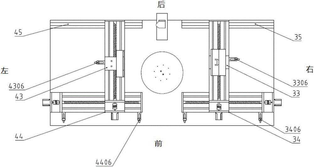
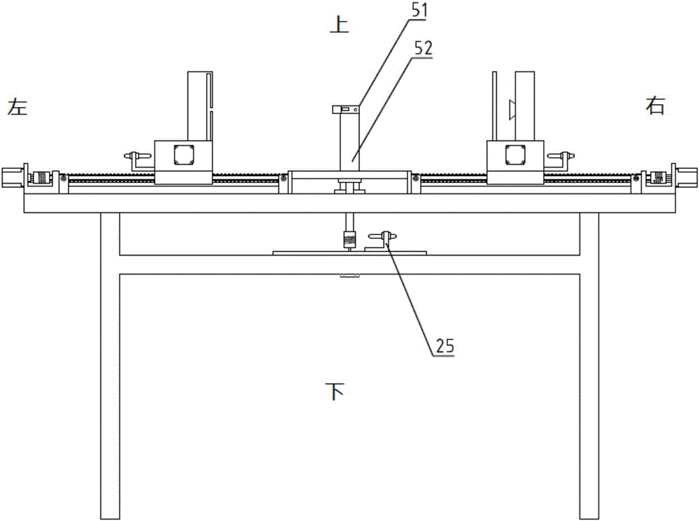
[0020] The present invention will be further explained in detail below in conjunction with the embodiments and the accompanying drawings, but this should not be used as a limitation to the protection scope of the claims of the present application. The orientation descriptions involved in this embodiment, such as front and rear, left and right, up and down, etc., are attached figure 1 , 2 , The orientation shown in 3 is for reference.

[0021] The present invention is based on an adaptive multimodal X-ray CT imaging scientific research experiment platform (CT platform for short, see Figure 1-6 ) includes a bearing platform 1, a central loading rotating platform component 2, an X-ray generator and a position moving component 3, an X-ray detector and a position moving component 4, and a distance measuring component 5; the bearing platform 1 is a table-shaped platform for supporting The role of all other components and imaging bodies; the central object rotating table assembly ...


PUM


Abstract

The invention relates to a self-adaptive multimode X-ray CT imaging scientific research experimental platform. The CT platform is characterized by comprising a bearing table, a center carrying rotary table assembly, an X-ray generator and location moving assembly, an X-ray detector and location moving assembly and a distance measuring assembly; the bearing table supports all other assemblies and an imaging object; the center carrying rotary table assembly is located at the center of the bearing table; the X-ray generator and location moving assembly is located on the right side of the center carrying rotary table assembly; the X-ray detector and location moving assembly is located on the left side of the center carrying rotary table assembly; the distance measuring assembly is located on the rear side of the center carrying rotary table assembly; the center carrying rotary table assembly comprises a carrying table, a connecting shaft, a coupler, a rotary table driving motor and a location switch; the carrying table is in a disc shape and is located on the surface of the bearing table; the connecting shaft penetrates through the surface of the bearing table, the upper portion of the connecting shaft is connected with the center point of the carrying table, and the lower portion of the connecting shaft is connected with the rotary table driving motor through the coupler.

Description

technical field [0001] The invention relates to the technical field of experimental teaching equipment for biomedical imaging scientific research, in particular to an adaptive multi-modal X-ray CT imaging scientific research experiment platform, which can perform adaptive adjustment of imaging modes and parameters, and the obtained X-ray CT . Background technique [0002] In the process of biomedical scientific research, it is one of the important fields of research to explore the internal organization and structure of living organisms or specimens in detail. X-ray imaging technology can generate images of the internal tissue structure of the researched object without destroying it, especially CT (computed tomography) technology can obtain three-dimensional images of the tissue structure of the organism. Therefore, X-ray CT has become one of the main methods for imaging the internal tissue structure of scientific research organisms (especially experimental animals). [000...

Claims


Application Information

Patent Timeline
Patent Type & Authority Applications(China)
IPC IPC(8): A61B6/03A61B6/04
CPCA61B6/032A61B6/4078A61B6/4085A61B6/4452A61B6/508A61B6/54A61B6/58A61B6/588A61B6/589A61B2503/40A61B6/0487
Inventor 韩立张雪君王晓东张顺心
Owner 韩立
Learn More