

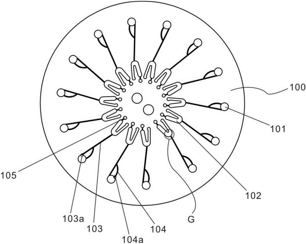
Centrifugal type multi-channel microfluidic chip
A microfluidic chip, multi-channel technology, used in fluid controllers, laboratory utensils, laboratory containers, etc., can solve the main flow bubble, increase the complexity of chip manufacturing, and cannot ensure that the liquid is always filled with the sample hole, etc. question
- Summary
- Abstract
- Description
- Claims
- Application Information
AI Technical Summary
Problems solved by technology
Method used
Image

Examples
Embodiment Construction
[0046] In order to make the above objects, features and advantages of the present invention more obvious and comprehensible, specific implementations of the present invention will be described in detail below in conjunction with the accompanying drawings.
[0047] In the following description, a lot of specific details are set forth in order to fully understand the present invention, but the present invention can also be implemented in other ways different from those described here, and those skilled in the art can do it without departing from the meaning of the present invention. By analogy, the present invention is therefore not limited to the specific examples disclosed below.
[0048] Second, "one embodiment" or "an embodiment" referred to herein refers to a specific feature, structure or characteristic that may be included in at least one implementation of the present invention. "In one embodiment" appearing in different places in this specification does not all refer to ...
PUM
 Abstract
Description
Claims
Application Information