A high-efficiency magnetic separation mechanism
A magnetic separation and high-efficiency technology, applied in the fields of magnetic separation, solid separation, chemical instruments and methods, etc., can solve the problems such as the inability to solve the contradiction between the grade of the finished ore and the recovery rate, the energy consumption of metal loss, and the reduction of the recovery rate, so as to improve the precision The effect of mineral taste, waste avoidance, and content reduction
- Summary
- Abstract
- Description
- Claims
- Application Information
AI Technical Summary
Problems solved by technology
Method used
Image
Examples
Embodiment 1
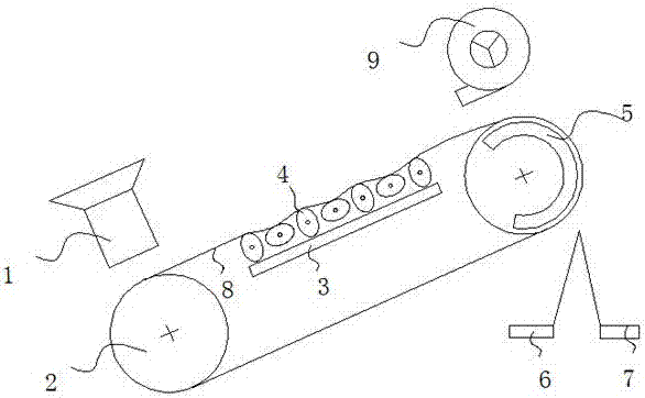
[0035] Such as figure 1 As shown, a kind of high-efficiency magnetic separation mechanism of the present invention, the present invention discloses a kind of high-efficiency magnetic separation mechanism, comprises the belt 8 that is used for mineral material conveying and the magnetic separation mechanism of mineral material output side; Belt 8 inner side is provided with for vibration The vibrating mechanism 4 of the mineral material above the belt 8.
[0036] The belt 8 inboard is also provided with a magnetic mechanism 3 .
[0037] The magnetic mechanism 3 is arranged below the vibration mechanism 4 . The magnetic field strength of the magnetic mechanism 3 decreases gradually along the conveying direction of the belt 8 , and the magnetic mechanism 3 adopts a structure in which N-S poles are alternately arranged.
[0038] The vibration mechanism 4 is a cam, an eccentric wheel, or a combination of a cam and an eccentric wheel, and the cam, an eccentric wheel, or a combinat...
Embodiment 2
[0046] Based on the magnetic separation mechanism of embodiment 1, its magnetic separation system includes a magnetic separation unit, a delivery unit, a vibration unit, a detection unit, and a control unit;
[0047] The conveying unit includes a belt, a driving wheel, a driven wheel, a driver, a conveying frame, a hydraulic device, and a hydraulic support column; the hydraulic supporting column is installed on the conveying frame, driven by a hydraulic device and controls the inclination angle of the belt, and the driving wheel and the driven wheel are installed separately On the conveyor frame, the belt is set between the driving wheel and the driven wheel, and the belt includes the upper belt and the lower belt; the driving wheel is driven by the driver, and the material is output from the side of the driven wheel; a fine hopper and a waste hopper are set under the driven wheel;
[0048] The vibration mechanism is arranged on the lower side of the upper belt and arranged alo...
Embodiment 3
[0054] Based on embodiment 1 and the magnetic separation mechanism and magnetic separation system of embodiment, its magnetic separation method is:
[0055] Step 1: Start the controller, the controller adjusts the belt to incline 20 degrees and convey the material at a speed of 0.6-0.7m / s, the control cam rotates at a speed of 60-70r / min, and the eccentric wheel rotates at a speed of 80-90r / min , the magnetic mechanism provides a magnetic field of 1200-1500 Gauss;
[0056] Step 2: The first weighing device measures the material weight m1 at the entrance of the conveying unit; the second weighing device measures the material weight m2 in the fine hopper, and the third weighing device measures the material weight m3 in the waste hopper; the controller collects m1, m2, the value of m3;
[0057] Step 3: When the ratio of m2 increment to m3 increment is less than 0.5, the speed of the control cam is increased by 20-30%, and the speed of the control eccentric wheel is increased by ...
PUM
 Abstract
Description
Claims
Application Information
 - R&D Engineer
- R&D Manager
- IP Professional
- Industry Leading Data Capabilities
- Powerful AI technology
- Patent DNA Extraction
Browse by: Latest US Patents, China's latest patents, Technical Efficacy Thesaurus, Application Domain, Technology Topic, Popular Technical Reports.
© 2024 PatSnap. All rights reserved.Legal|Privacy policy|Modern Slavery Act Transparency Statement|Sitemap|About US| Contact US: help@patsnap.com


