Nozzle flow rotating generation device and nozzle flow rotating continuous casting method

A generating device and swirl generator technology, which is applied to casting equipment, casting molten material containers, metal processing equipment, etc., can solve the problem of affecting the service life of the submerged nozzle, the guide groove is easily blocked or eroded, and the swirl strength is weakened, etc. problems, to achieve the effect of reducing nozzle nodules, preventing nozzle clogging, and improving flow conditions

Active Publication Date: 2016-09-28
NORTHEASTERN UNIV
View PDF6 Cites 8 Cited by
  • Summary
  • Abstract
  • Description
  • Claims
  • Application Information

AI Technical Summary

Problems solved by technology

For the electromagnetic swirl method, the electromagnetic force that generates the swirl needs to be provided by consuming electric energy, and the electromagnetic swirl device also needs to spend a lot of equipment costs
For the blade swirling method, there is always a shortcoming in blade life, and the deposition of non-metallic inclusions on the blade surface can easily lead to blockage of the nozzle
For the guide groove swirl method, it is not easy to process a spiral guide groove on the inner wall of the submerged nozzle, and the guide groove is easily blocked or corroded, which weakens the swirl strength and affects the service life of the submerged nozzle

Method used


Image

  • Nozzle flow rotating generation device and nozzle flow rotating continuous casting method
  • Nozzle flow rotating generation device and nozzle flow rotating continuous casting method
  • Nozzle flow rotating generation device and nozzle flow rotating continuous casting method

Examples


specific Embodiment

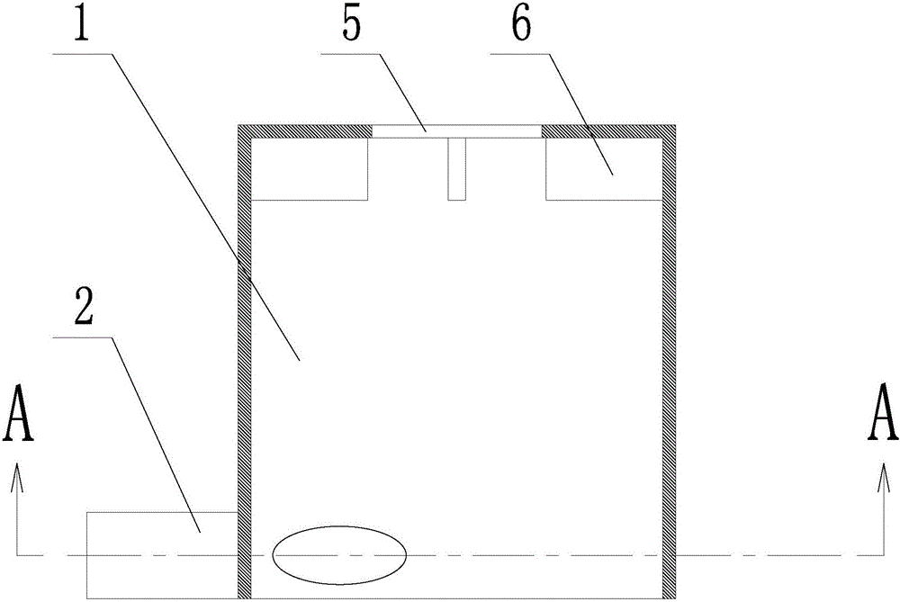
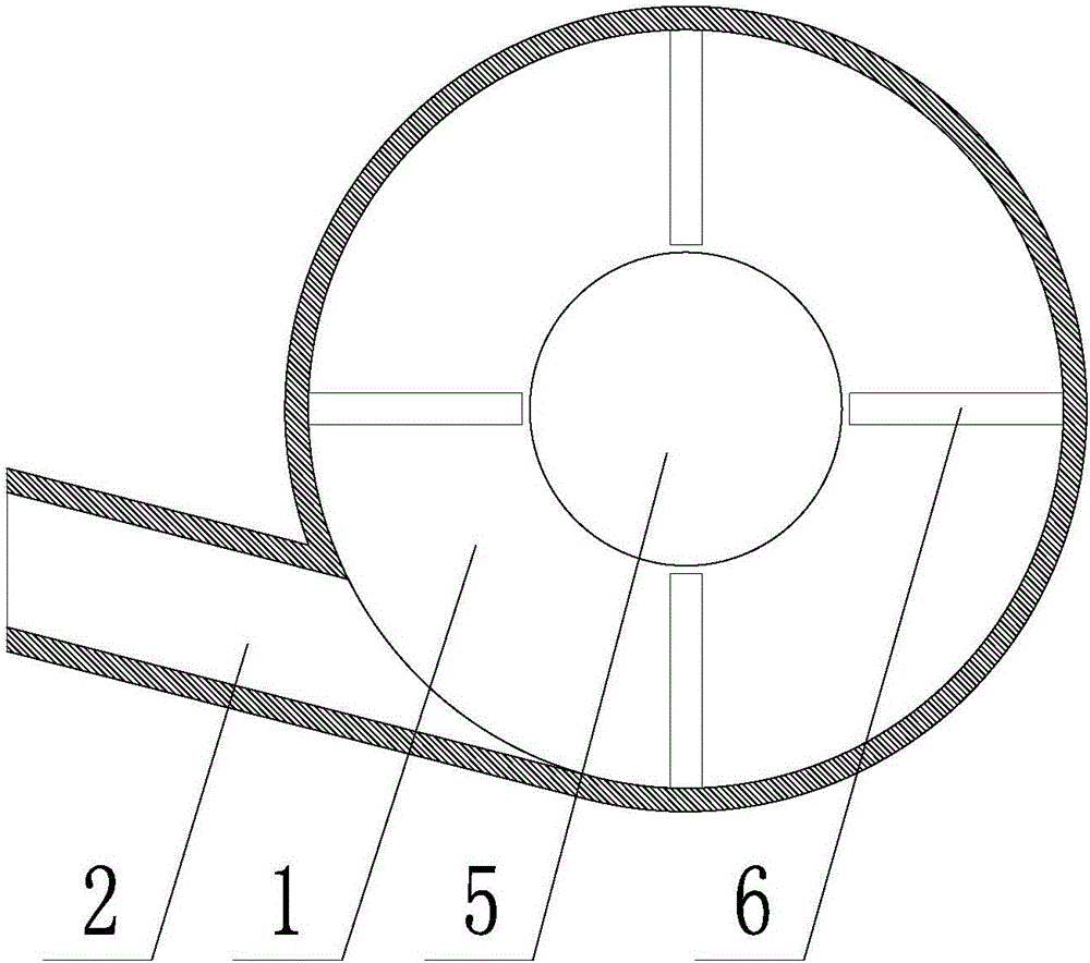
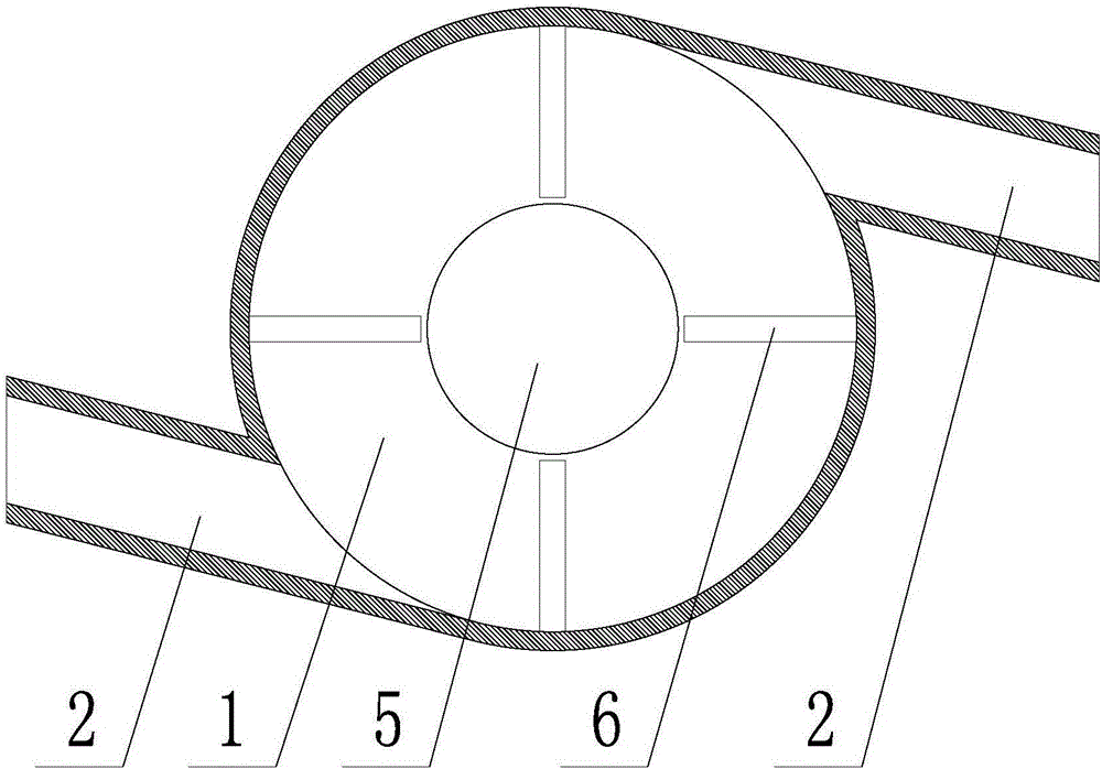
[0052] In the continuous casting production process, the size of the cylindrical swirl generator and the cylindrical swirl tundish can be set according to the actual production capacity requirements. The specific dimensions are as follows:

[0053] Cylindrical swirl generator: the generator cylinder 1 can be of equal diameter structure or variable diameter structure. When the equal diameter structure is preferred, the inner diameter of the generator cylinder 1 is 100mm-500mm, and the generator molten steel inlet 2 can be a circular pipe , rectangular tube or other shape tubes, preferably circular tubes, the inner diameter of the generator molten steel inlet 2 is 10 mm to 100 mm, the number of generator molten steel inlets 2 is preferably 1 to 2, and the number of slag retaining weirs 6 is preferably 4 and can be cuboid The length, width and height of the slag retaining weir 6 are 20mm-100mm, 20mm-50mm and 20mm-200mm respectively.

[0054] Cylindrical swirling tundish: the tund...


PUM


Abstract

The invention discloses a nozzle flow rotating generation device and a nozzle flow rotating continuous casting method. The device comprises a cylinder type flow rotating generator and a cylinder type flow rotating tundish; the cylinder type flow rotating generator is mounted in a traditional continuous casting tundish, and an inner cavity of the traditional continuous casting tundish is communicated with an immersion type nozzle through the cylinder type flow rotating generator; the cylinder type flow rotating tundish has two mounting modes; according to the first mode, the cylinder type flow rotating tundish and the traditional continuous casting tundish are used in a cooperated manner, the cylinder type flow rotating tundish is mounted on the outer portion of the traditional continuous casting tundish, and the traditional continuous casting tundish is communicated with the immersion type nozzle through the cylinder type flow rotating tundish; and according to the second mode, the cylinder type flow rotating tundish is independently used, and a nozzle of a steel ladle is communicated with the immersion type nozzle directly through the cylinder type flow rotating tundish. The method comprises the steps that before continuous casting, according to the continuous casting technology, the nozzle flow rotating generation device is selected, then, the device and the traditional continuous casting tundish are assembled, during continuous casting, under the effects of molten steel gravity and tangent line entrances, molten steel generates rotating flowing, and molten steel in the immersing type nozzle generates rotary flowing.

Description

technical field [0001] The invention belongs to the technical field of metal liquid pouring in the metallurgical industry, and in particular relates to a nozzle swirl flow generating device and a nozzle swirl continuous casting method. Background technique [0002] The quality of iron and steel products is crucial to improving the competitiveness of iron and steel enterprises, and the production process of continuous casting of iron and steel is an important part of determining the quality of iron and steel products. In the continuous casting process of iron and steel, after passing through the ladle and the tundish, the molten steel will flow into the crystallizer through the submerged nozzle connected to the tundish, and cool and solidify in the mold to form a slab, while the flow of molten steel in the mold Field, temperature field and the stability of molten steel liquid level are crucial to the quality of casting slab. [0003] Since the flow behavior of molten steel i...

Claims


Application Information

Patent Timeline
Patent Type & Authority Applications(China)
IPC IPC(8): B22D41/50B22D41/00
CPCB22D41/00B22D41/507
Inventor 厉英倪培远
Owner NORTHEASTERN UNIV
Why Eureka
Try Eureka