Crankshaft machining clamp

A crankshaft processing and fixture technology, which is applied in the direction of manufacturing tools, metal processing equipment, metal processing machinery parts, etc., can solve the problems of complex crankshaft structure, uneven weight distribution of inertial motion, and falling off of the crankshaft, and achieve cost reduction and inertial motion weight. evenly distributed effect

Inactive Publication Date: 2016-09-28
JIANGSU HEFUTE GEAR MFG
View PDF6 Cites 1 Cited by
  • Summary
  • Abstract
  • Description
  • Claims
  • Application Information

AI Technical Summary

Problems solved by technology

[0002] Crankshafts are used more and more widely, and are often used in steel rolling, papermaking and other production lines. Crankshafts are one of the important components to ensure the shearing quality of products. In the past, all crankshafts were processed by outsourced special machine tools, with high cost and long cycle time.
The difficulty of crankshaft machining is mainly reflected in two aspects: (1) The structure of the crankshaft is complex, and it is difficult to determine the center of rotation on the lathe; (2) When machining the crankshaft rotary motion, the inertial motion weight distribution is uneven, which affects the machining accuracy, and the crankshaft rotates quickly It is also easy to cause the crankshaft to fall off from the clamping position of the machine tool

Method used


Image

  • Crankshaft machining clamp
  • Crankshaft machining clamp

Examples


Embodiment Construction

[0017] The present invention is described in further detail now in conjunction with accompanying drawing. These drawings are all simplified schematic diagrams, which only illustrate the basic structure of the present invention in a schematic manner, so they only show the configurations related to the present invention.

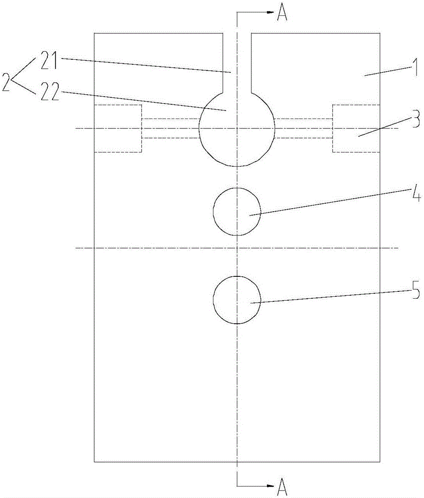
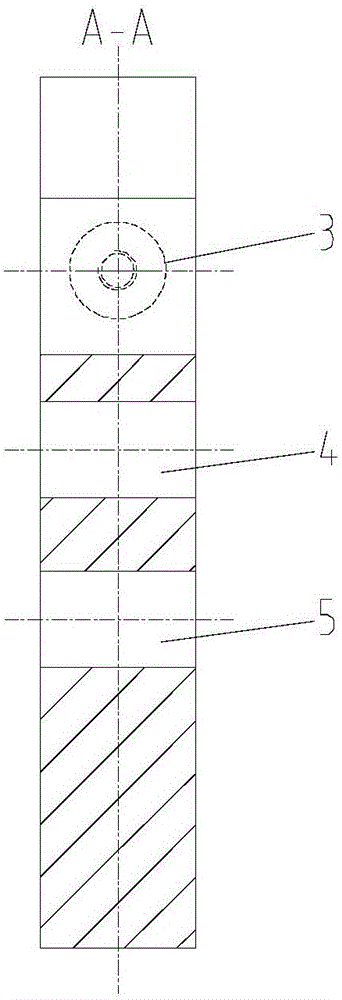
[0018] See figure 1 and figure 2 , a crankshaft processing fixture of the present invention has a rectangular fixture body 1 arranged opposite to the balance weight of the flying shear crankshaft, and a clamping channel matching the outer end of the short axis of the flying shear crankshaft is provided in the thickness direction of the rectangular fixture body 1 Hole 2, two fixed threaded holes 3 located on both sides of the clamping through hole 2 are opened symmetrically in the width direction of the rectangular fixture body 1, and there are also holes corresponding to the position of the four-jaw chuck in the thickness direction of the rectangular fixture...


PUM


Abstract

The invention relates to the technical field of fixtures, in particular to a crankshaft processing fixture, which has a rectangular fixture body arranged opposite to the balance weight of the flying shear crankshaft. There are two fixed threaded holes located on both sides of the clamping through hole symmetrically in the width direction of the rectangular fixture body, and there are also provided in the thickness direction of the rectangular fixture body corresponding to the position of the four-jaw chuck. The corresponding fixing through hole and the correction through hole on a straight line with the major axis of the flying shear crankshaft. The fixture can control the quality and cycle of crankshaft processing and reduce the cost.

Description

technical field [0001] The invention relates to the technical field of fixtures, in particular to a crankshaft machining fixture. Background technique [0002] Crankshafts are used more and more widely. They are often used in steel rolling, papermaking and other production lines. Crankshafts are one of the important components to ensure the shear quality of products. In the past, all crankshafts were processed by outsourced special machine tools, with high cost and long cycle time. The difficulty of crankshaft machining is mainly reflected in two aspects: (1) The structure of the crankshaft is complex, and it is difficult to determine the center of rotation on the lathe; (2) When machining the crankshaft rotary motion, the inertial motion weight distribution is uneven, which affects the machining accuracy, and the crankshaft rotates quickly It is also easy to cause the crankshaft to fall off from the clamping position of the machine tool. Contents of the invention [0003...

Claims


Application Information

Patent Timeline
Patent Type & Authority Applications(China)
IPC IPC(8): B23Q3/12
CPCB23Q3/12B23Q2703/105
Inventor 钱江宋廷王福龙
Owner JIANGSU HEFUTE GEAR MFG
Why Eureka
Try Eureka