Brazing filler metal for joining, composite part and cutting tool using the brazing filler metal for joining

A technology of composite parts and joints, which is applied to tools for lathes, parts of boring machines/drilling machines, and manufacturing tools, etc., which can solve the problems of reduced mechanical properties of tool bases, insufficient adhesion strength, and inability to obtain sufficient joint strength. , to achieve the effect of excellent cutting performance

Active Publication Date: 2018-05-01
MITSUBISHI MATERIALS CORP
View PDF14 Cites 0 Cited by
  • Summary
  • Abstract
  • Description
  • Claims
  • Application Information

AI Technical Summary

Problems solved by technology

[0012] However, the cutting tool disclosed in Patent Document 1 obtains strong bonding strength by using Ti-based metals. However, if Ti is excessively diffused, the mechanical properties of the tool base made of hard alloy on the side of the hard shank and the cutting edge will be reduced. , there is a problem that causes damage
[0013] In addition, in the Ag-based solder disclosed in Patent Document 2, Ag has low mechanical strength, so sufficient bonding strength cannot be obtained.
[0014] In the bonded body having a titanium nitride compound layer of 10 to 300 nm disclosed in Patent Document 3, there is a problem that the reaction between the bonding material and the cBN-based sintered body is not appropriate, and sufficient bonding strength cannot be obtained.
[0015] In addition, in the bonding using conventional brazing filler metals, the adhesion strength between the cBN sintered body and the tool substrate made of cemented carbide is not sufficient, so when it is used for heavy cutting, the cBN sintered body may fall off from the joint and reach the tool. The subject of longevity

Method used


Image

  • Brazing filler metal for joining, composite part and cutting tool using the brazing filler metal for joining
  • Brazing filler metal for joining, composite part and cutting tool using the brazing filler metal for joining
  • Brazing filler metal for joining, composite part and cutting tool using the brazing filler metal for joining

Examples


Embodiment

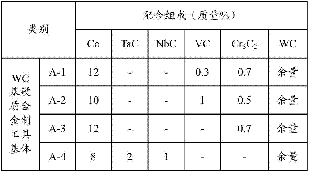
[0067] As raw material powders, WC powder, VC powder, TaC powder, NbC powder, Cr 3 C 2 powder and Co powder. These raw material powders were mixed into the compounding composition shown in Table 1, and wet mixed with a ball mill for 24 hours. After drying, the compact was formed into a compact with a pressure of 100 MPa, and the compact was placed in a vacuum of 6 Pa at Sintering was carried out at a temperature of 1400° C. and a holding time of 1 hour to form four types of WC-based hard tool substrates (hereinafter, simply referred to as hard tool substrates) A-1 to A-4 shown in Table 1.

[0068] [Table 1]

[0069]

[0070] Next, cBN powder, TiN powder, TiCN powder, TiB 2 powder, TiC powder, AlN powder, Al 2 o 3 Powder, these raw material powders are blended with a prescribed blending composition, wet-mixed with acetone for 24 hours using a ball mill, after drying, press-molded into a green compact with a size of 15 mm in diameter × 1 mm in thickness, and then, the Th...


PUM

PropertyMeasurementUnit
widthaaaaaaaaaa
thicknessaaaaaaaaaa
thicknessaaaaaaaaaa

Abstract

A cutting tool including a cutting edge part made of cBN sintered material bonded through a brazing material for bonding and a cutting tool body made of WC-based cemented carbide is provided. In the cutting tool, the cutting edge part made of cBN sintered material and the cutting tool body made of WC-based cemented carbide are brazed by using a blazing material for bonding including: 35-40% of Ti in a mass ratio; 35-40% of Zr in a mass ratio; 5-15% of Ni in a mass ratio; and the Cu balance including inevitable impurities.

Description

technical field [0001] The present invention relates to a brazing filler metal for joining, a composite part and a cutting tool using the brazing filler metal for joining, and more specifically, relates to an improved method for joining cubic boron nitride (hereinafter referred to as cBN) sintered bodies and cutting tools. Brazing filler metals for bonding strength of cemented carbide, and composite parts and cutting tools using the brazing filler metals. [0002] This application claims priority based on Patent Application No. 2013-266912 filed in Japan on December 25, 2013 and Patent Application No. 2014-256468 filed in Japan on December 18, 2014, and the contents thereof are incorporated herein. Background technique [0003] In recent years, cutting tools such as inserts and end mills using cBN sintered bodies for cutting edges have been provided as tools for processing metal molds used in manufacturing housings of mobile phones, smartphones, and the like. This cBN sinte...

Claims


Application Information

Patent Timeline
Patent Type & Authority Patents(China)
IPC IPC(8): B23K35/32B23B27/18B23K35/40C22C29/08C22C30/02
CPCB23K35/325B22F7/064B23B27/18B23B2222/28B23B2226/125B23B2240/08B23K35/005B23K35/32B23K35/327B23K35/40B23K2101/20C22C1/0458C22C14/00C22C29/08C22C30/02C22C2204/00
Inventor 五十岚诚大桥忠一油本宪志清水博康
Owner MITSUBISHI MATERIALS CORP
Why Eureka
Try Eureka