A circular product injection mold with a push-rod slide block demoulding structure

A sliding block and circular technology, which is applied in the field of injection molds for round products, can solve the problems of increased processing cost, large size of the sliding block, and many sliding blocks, and achieves improved product quality, simple demolding structure, and accurate demolding position. Effect

Active Publication Date: 2018-02-23
广东健大电业有限公司
View PDF7 Cites 0 Cited by
  • Summary
  • Abstract
  • Description
  • Claims
  • Application Information

AI Technical Summary

Problems solved by technology

This method has the following disadvantages: first, there are many sliders, and each slider is not easy to fix; second, the volume of the slider is relatively large;
The traditional sliding block demoulding method makes the actual mold opening distance of the mold large, and the slider is large in size, which wastes space and increases processing costs, making demoulding difficult and difficult to maintain

Method used


Image

  • A circular product injection mold with a push-rod slide block demoulding structure
  • A circular product injection mold with a push-rod slide block demoulding structure
  • A circular product injection mold with a push-rod slide block demoulding structure

Examples


Embodiment Construction

[0012] The preferred embodiments of the present invention will be described in detail below in conjunction with the accompanying drawings, so that the advantages and features of the present invention can be more easily understood by those skilled in the art, so as to define the protection scope of the present invention more clearly.

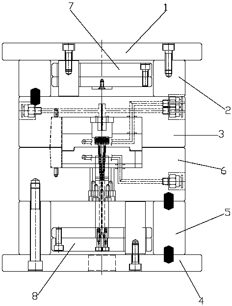
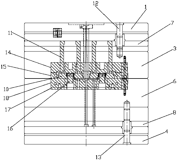
[0013] Such as Figure 1 to Figure 4 As shown, a circular product injection mold with a push rod type slider demoulding structure includes a front mold and a rear mold, the front mold includes a panel 1, two front mold feet 2 vertically arranged on the rear side of the panel 1 And the front template 3 that is horizontally arranged on the two front mold feet 2, the back mold includes a base plate 4, two rear mold feet 5 vertically arranged on the front side of the base plate 4 and two rear mold feet 5 that are horizontally arranged on the two rear mold feet 5 Back formwork 6, front formwork top plate 7 is provided between two front mold feet 2, re...


PUM


Abstract

The invention discloses a circular product injection mold with a push rod type sliding block demolding structure. The injection mold comprises a front mold and a back mold, wherein the front mold comprises a panel, two front mold feet and a front mold plate; the back mold comprises a bottom plate, two back mold feet and a back mold plate; a front mold ejection plate is arranged between the two front mold feet; a back mold ejection plate is arranged between the two back mold feet; a front mold core assembly is arranged in the front mold plate; a back mold core assembly is arranged in the back mold plate; front mold cavities are formed in the front mold core assembly; sliding block cavities are formed outside outer circumferences of the front mold cavities; sliding blocks are arranged in the sliding block cavities; ends of the multiple sliding blocks are assembled to form circular cavity walls of an injection molding cavity; push rods are arranged on the front mold ejection plate and can act on the sliding blocks; one side, far away from the front mold cavity, of each sliding block is an inclined surface; and the sliding block cavities also comprise inclined surface cavities walls matched with the inclined surfaces of the sliding blocks. According to the injection mold, the size of the sliding blocks is small, the demolding structure is simple, the machining cost of the mold is reduced, the whole mold runs stably, the sliding blocks can move synchronously, the demolding position is accurate, and the product quality is improved.

Description

technical field [0001] The invention relates to the technical field of moulds, in particular to a circular product injection mold with a push-rod type slide block demoulding structure. Background technique [0002] For some round products, due to their small volume and the circular undercut on the circumference, more sliders are needed to splice into round products. After injection molding, it needs to be demolded by a slider. The traditional slider demoulding is to complete the reverse buckle demoulding of the product by pulling the core out of the inclined guide post. This method has the following disadvantages: one is that there are many sliders, and each slider is not easy to fix; The traditional sliding block demoulding method makes the actual mold opening distance of the mold large, and the volume of the slider is large, which not only wastes space but also increases processing costs, making demoulding difficult and difficult to maintain. Contents of the invention ...

Claims


Application Information

Patent Timeline
Patent Type & Authority Patents(China)
IPC IPC(8): B29C45/32B29C45/40
CPCB29C45/32B29C45/4005
Inventor 蔡峻峰喻一峰王前程
Owner 广东健大电业有限公司
Why Eureka
Try Eureka