
A water craft or flying craft having a propeller

A technology of propulsion and tools, applied in the direction of ship propulsion, propulsion components, power plant types, etc., can solve the problems of increasing the loss of pumping energy, affecting the control experience, reducing the propulsion force, etc., to improve propulsion efficiency, flexible operation, The effect of reducing power loss

Active Publication Date: 2018-10-12
王前进
View PDF6 Cites 0 Cited by
  • Summary
  • Abstract
  • Description
  • Claims
  • Application Information

AI Technical Summary

Problems solved by technology

[0002] There are many types of pump-jet propellers used in existing water tools or aircraft, but due to the large volume of traditional pump-jet propellers, it is inconvenient to install, coupled with the limitation of its structure, the flow channel inlet, usually with There is a transitional linear curve between the injection ports, which increases the energy loss of the pump injection, thereby greatly reducing the propulsion and affecting the handling experience

Method used


Image

  • A water craft or flying craft having a propeller
  • A water craft or flying craft having a propeller
  • A water craft or flying craft having a propeller

Examples


Embodiment 1

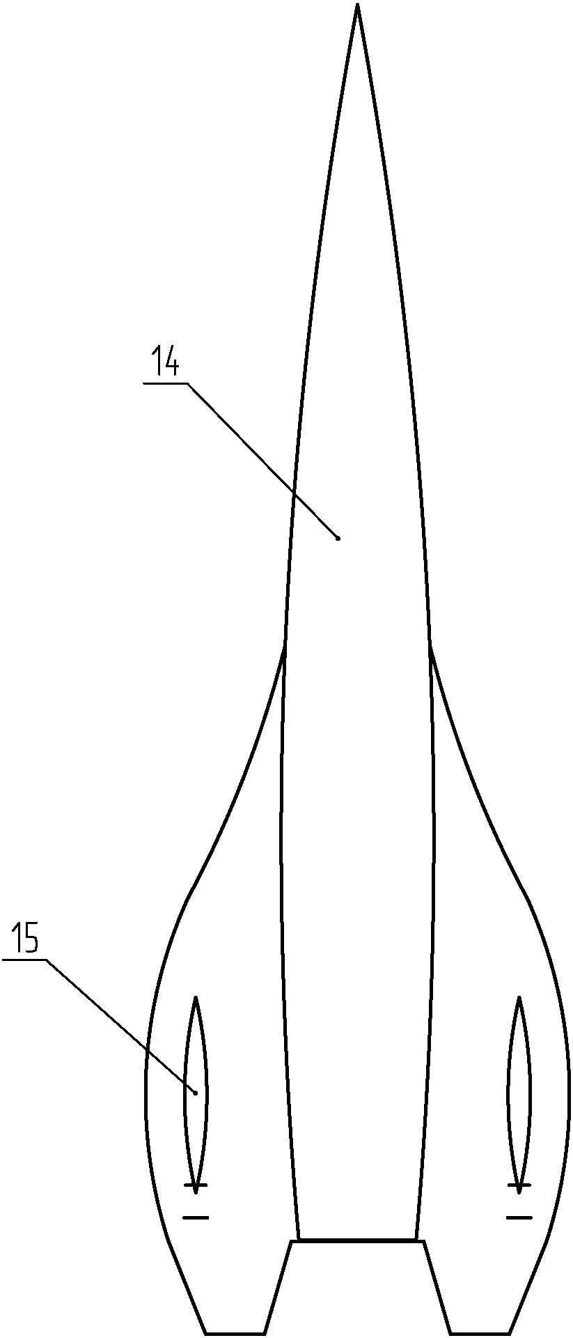
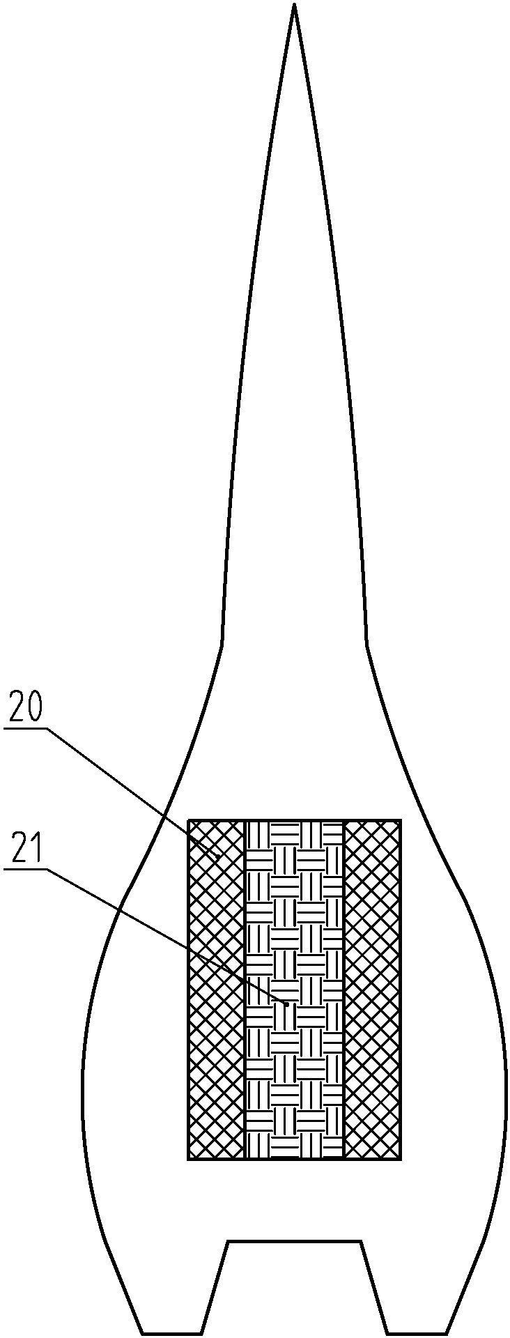
[0035] like Figures 1 to 6 As shown, a water tool with an improved thruster includes a tool body 14, two guide bodies 15, two propulsion devices, a control device, a control device, and a power supply device.

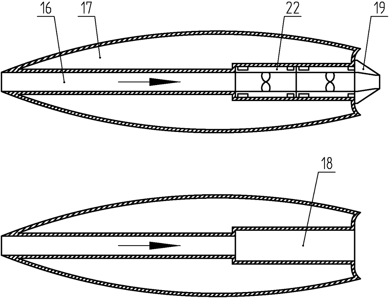
[0036] The guide body 15 is spindle-shaped, and it is symmetrically installed on the left and right sides of the bottom end of the tool body 14. The inside of the guide body 15 is provided with a closed cavity 17 that provides buoyancy, and a flow channel 16 is provided along the axial direction of the guide body 15. 16 rear and the installation hole 18 that communicates with its coaxial, respectively install a propulsion device in each installation hole 18.

[0037] Each propulsion device comprises two propellers 22 installed in series before and after, the propeller 22 positioned at the front is a primary propeller, and the propeller 22 positioned at the rear is a secondary propeller; The inner diameters of the Venturi tube 19 and the Venturi tube 19 decrease sequen...

Embodiment 2

[0050] The difference from Embodiment 1 is that in this embodiment, the number of propulsion devices is one, and the control device only includes a speed sensor, and the speed is adjusted by stepping on the speed sensing area on the surface of the water skateboard, while the steering is performed by swinging the limbs Realize, similar to the steering of the ground skateboard.

Embodiment 3

[0052] The difference from Embodiment 1 is that in this embodiment, the control device can capture body movements instead of pressure sensing, that is, the somatosensory camera recognizes specific body commands and converts them into control signals and transmits them to the control device for manipulation.


PUM


Abstract

The invention discloses a watercraft or aircraft provided with improved thrusters. The watercraft or aircraft is characterized by comprising a craft body, at least one thrusting device, a control device, an operation device and a power supply device, wherein the at least one thrusting device is mounted on the craft body and used for providing power; the control device is mounted inside the craft body and used for receiving operation signals sent out by the operation device so as to control the at least one thrusting device to work; the power supply device is mounted inside the craft body and used for providing electric energy for the at least one thrusting device and the control device. The watercraft or aircraft has the beneficial effects as follows: the watercraft or aircraft adopts the through flow guiding body design, the power loss of a water suction port of the pump-jet thrusters can be effectively reduced, and the thrusting efficiency can be improved; the jet velocity is greatly increased by the aid of the combination of multiple stages of annular pump-jet thrusters, jet pressure heads are increased, and the combination is a high-speed thruster combination; the watercraft or aircraft can realize intelligent sensing and is flexible to operate and simple in structure.

Description

technical field [0001] The invention belongs to the technical field of fluid propellers, and in particular relates to a water tool or a flying tool with a propeller. Background technique [0002] There are many types of pump-jet propellers used in existing water tools or aircraft, but due to the large volume of traditional pump-jet propellers, it is inconvenient to install, coupled with the limitation of its structure, the flow channel inlet, usually with There is a transitional linear curve between the injection ports, which increases the energy loss of the pump injection, thereby greatly reducing the propulsion and affecting the handling experience. Contents of the invention [0003] The object of the present invention is to overcome the deficiencies in the prior art and provide a water tool or flying tool with a propeller, which has a large propulsion force and is convenient for intelligent control. [0004] In order to solve the problems in the prior art, the present ...

Claims


Application Information

Patent Timeline
Patent Type & Authority Patents(China)
IPC IPC(8): B63H11/04B64D27/16
CPCB63H11/04B64D27/16
Inventor 王前进
Owner 王前进
Learn More