
A quick-loading protective sleeve structure for drilling tools

A protective cover and quick-installation technology, which is applied in the directions of packaging, transportation, packaging, closing, etc., can solve the problems of laborious installation or removal operation, large axial distance of the protective cover, and few times of repeated use, etc. The effect of small space, simple structure and fast speed

Inactive Publication Date: 2018-06-26
东莞市瑞佳机电工程有限公司
View PDF5 Cites 0 Cited by
  • Summary
  • Abstract
  • Description
  • Claims
  • Application Information

AI Technical Summary

Problems solved by technology

The existing protective sleeve and drilling tools are screw-mounted, and both the installation and removal operations are laborious, and the number of times of repeated use is small, so the cost is also high
On the same day, the applicant applied for a patent titled "Quick Mounting Protective Cover for Drilling Tools", which can be quickly installed on the drilling tool and quickly removed, and is easy to use; however, in the above patent, the operating wheel used extends out The end face of the protective sleeve leads to a large axial distance of the protective sleeve, which affects the spatial arrangement to a certain extent

Method used


Image

  • A quick-loading protective sleeve structure for drilling tools
  • A quick-loading protective sleeve structure for drilling tools
  • A quick-loading protective sleeve structure for drilling tools

Examples


Embodiment Construction

[0014] The specific embodiments of the present invention will be further described below in conjunction with the accompanying drawings.

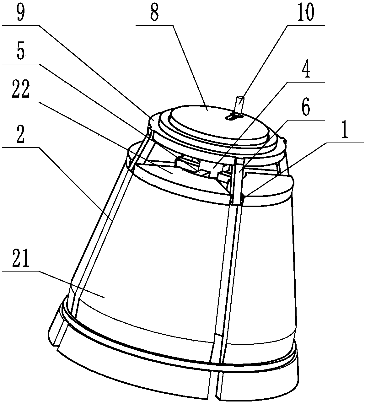
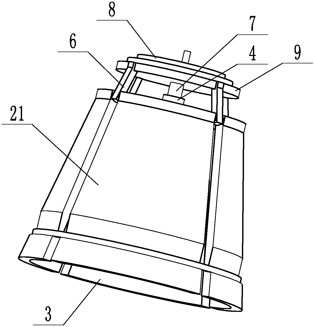
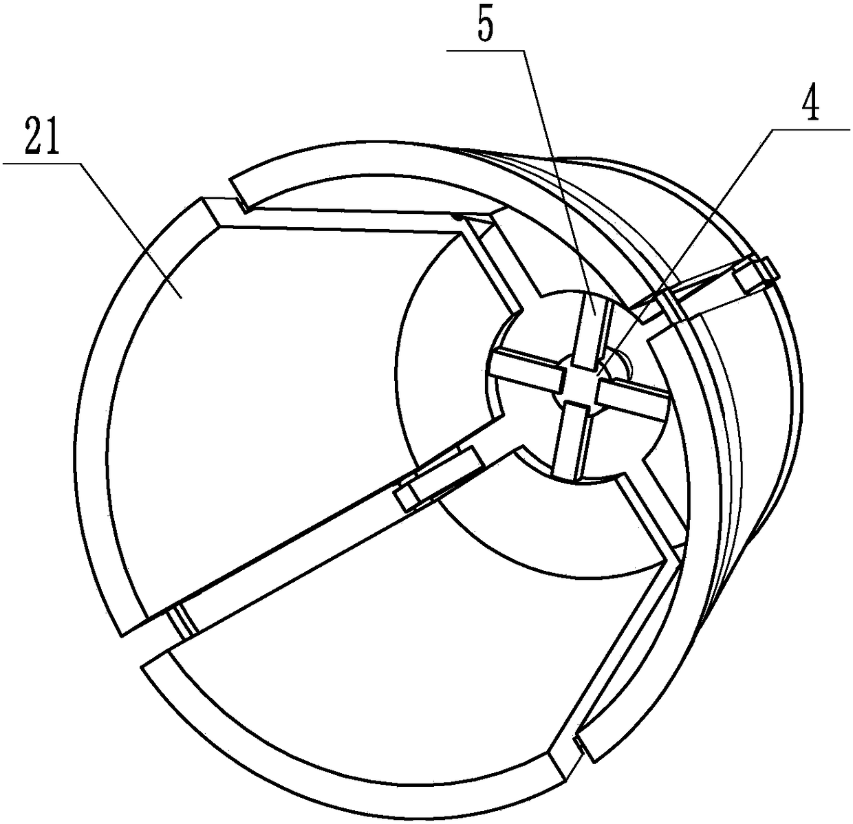
[0015] Such as Figure 1 to Figure 3 As shown, the quick-loading protective sleeve structure of the drilling tool in this embodiment includes a protective ring 1, and a plurality of protective sheets 2 are arranged at intervals along the circumferential direction of the protective ring 1, and the plurality of protective sheets 2 form a cone shape as a whole. The protection chamber 3, the drilling tool is placed in the protection chamber 3; the protection sheet 2 includes a wrapping sheet 21 for wrapping the drilling tool and a swing sheet 22 placed in the protection ring 1, the swing sheet 22 and the wrapping sheet 21 are Formed in one piece, the connecting turning point of the swinging piece 22 and the wrapping piece 21 is rotated and installed on the protection ring 1, and an adjusting sleeve 4 is arranged in the center of the enclosed are...


PUM


Abstract

The invention relates to a quick-assembly protective sleeve structure of a drilling tool. The quick-assembly protective sleeve structure comprises a protective ring, wherein a plurality of protective pieces are arranged in the circumferential direction of the protective ring in a spaced manner; a tapered protective cavity is integrally formed among the protective pieces; the drilling tool is arranged in the protective cavity; the protective pieces comprise wrapping pieces for wrapping the drilling tool, and swinging pieces arranged in the protective ring; the swinging pieces and the wrapping pieces are integrally formed; connection and bending parts between the swinging pieces and the wrapping pieces are rotationally mounted on the protective ring; a regulating sleeve is arranged in the center of a zone defined by the swinging pieces; a connecting rod is connected between the regulating sleeve and one swinging piece correspondingly; one end of one connecting rod is fixedly connected with one swinging piece correspondingly; the other ends of the connecting rods are hinged to the side wall of the regulating sleeve; a fixing plate is mounted at one side of the axial direction of the protective ring, and is fixedly connected with the protective ring through fixing rods; a spiral short column is rotationally mounted in the center of the fixing plate; the inner end of the spiral short column is spirally mounted in the regulating sleeve; an operating panel is mounted at the outer end of the spiral short column; and a handle is mounted at the side surface of the operating panel.

Description

technical field [0001] The invention relates to a protective sleeve of a drilling tool for geological exploration. Background technique [0002] In order to prevent damage to the thread at the end of the drilling tool, it is generally necessary to install a protective sleeve on the threaded end. The existing protective sleeve and the drilling tool are spirally installed, and both the installation operation and the removal operation are relatively laborious, and the number of times of repeated use is relatively small, so the cost is also relatively high. On the same day, the applicant applied for a patent titled "Quick Mounting Protective Cover for Drilling Tools", which can be quickly installed on the drilling tool and quickly removed, and is easy to use; however, in the above patent, the operating wheel used extends out The end face of the protective sleeve leads to a large axial distance of the protective sleeve, which affects the spatial arrangement to a certain extent. ...

Claims


Application Information

Patent Timeline
Patent Type & Authority Patents(China)
IPC IPC(8): B65D59/04
CPCB65D59/04
Inventor 陈登云
Owner 东莞市瑞佳机电工程有限公司
Learn More