High-strength thread rolling machine

A thread rolling machine and high-strength technology, applied in the field of thread rolling machines, can solve the problems of product quality decline, motor overload, and output quality reduction, and achieve the advantages of convenient manufacturing and installation, improved service life, and improved lining strength. Effect

Inactive Publication Date: 2016-09-28
ZHUCHENG ZENGYI ENVIRONMENTAL PROTECTION EQUIP CO LTD
View PDF0 Cites 2 Cited by
  • Summary
  • Abstract
  • Description
  • Claims
  • Application Information

AI Technical Summary

Problems solved by technology

[0003] 1. The transmission connection is a cross-shaped coupling, which is noisy and easy to wear. After wear, the bearing is prone to damage, which leads to a reduction in the fit of the thread rolling wheel, tooth beating, damage, and safety accidents.
[0004] 2. The screw conveying blade on the main shaft of the equipment is easy to be entangled by long fibers, causing the phenomenon of drum cover and overloading of the motor
[0005] 3. The thickness of the cutter roll is relatively thin, the teeth are too dense, and the teeth are easy to break
[0006] 4. The machine body is a cast iron multi-part assembly structure, and the errors accumulated in processing, manufacturing and installation make it difficult to guarantee the matching accuracy of the thread rolling wheel, shorten the service life of the equipment, and reduce the product quality
[0007] 5. The lining material of the upper and lower machine covers is cast iron, which is easy to wear and tear, resulting in a larger gap between the thread rolling wheel and the machine cover, and a lower quality of the output.

Method used


Image

  • High-strength thread rolling machine
  • High-strength thread rolling machine
  • High-strength thread rolling machine

Examples


Embodiment Construction

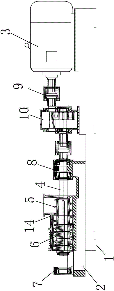
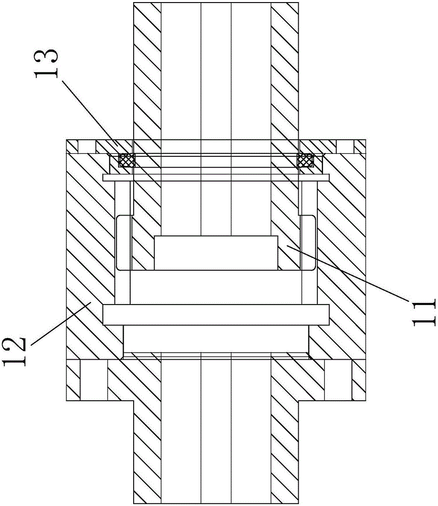
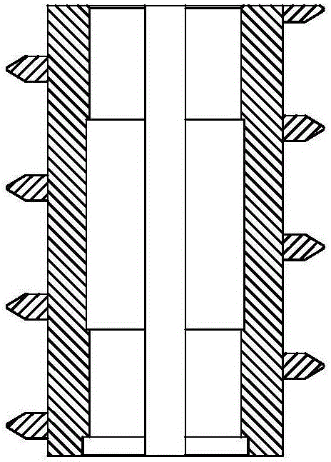
[0022] Such as Figure 1-6 As shown, a high-strength thread rolling machine includes a base 1 and a body 2. One end of the base 1 is provided with an organic body 2, and the other end is equipped with a drive motor 3. The inside of the body 2 is provided with two parallel plug-in rotating shafts 4. The feed end of the rotating shaft 4 is respectively provided with helical cutting blades 5 with opposite helical directions, and the discharge end of the plugged rotating shaft 4 is respectively provided with knife rollers 6, and the discharge end of the plugged rotating shaft 4 passes through a detachable bearing. The seat 7 is fixed on the body 2, and the feeding end of the plug-in rotating shaft 4 runs through the bearing sleeve 8 of the body 2 and is rotationally connected with the gearbox 10 through the gear coupling 9. The driving motor 3 is also connected with the gearbox through the gear coupling 9. 10 rotation connection, the gear coupling 9 is composed of an inner gear di...


PUM


Abstract

A high-strength thread rolling machine, including a base and a body, an organic body is installed at one end of the base, a drive motor is installed at the other end, two parallel plug-in rotating shafts are arranged inside the body, and the feeding of the plug-in rotating shafts Helical cutting blades with opposite helical directions are respectively arranged on the end parts, and knife rollers are respectively arranged on the discharge end parts of the plug-in rotating shaft, and the discharge end of the plug-in rotating shaft is fixed on the machine body through a detachable bearing seat, so The feed end of the plug-in rotating shaft runs through the bearing sleeve of the machine body and is rotatably connected with the gearbox through a gear coupling, and the driving motor is also rotatably connected with the gearbox through a gear coupling. The invention has low noise, the bearing is not easy to be damaged, and the phenomenon that the main shaft is not entangled by long fibers occurs.

Description

technical field [0001] The invention relates to a thread rolling machine, in particular to a high-strength thread rolling machine. Background technique [0002] At present, there are the following problems in the grinding and dividing machine: [0003] 1. The transmission connection is a cross-shaped coupling, which is noisy and easy to wear. After wear, the bearing is prone to damage, which leads to a reduction in the fit of the thread rolling wheel, tooth beating, damage, and safety accidents. [0004] 2. The screw conveying blade on the main shaft of the equipment is easily entangled by long fibers, causing the phenomenon of drum cover and overloading of the motor. [0005] 3. The thickness of the knife roller is relatively thin, and the teeth are too dense, which is easy to break the teeth. [0006] 4. The machine body is a cast iron multi-part assembly structure, and the errors accumulated in processing, manufacturing and installation make it difficult to guarantee th...

Claims


Application Information

Patent Timeline
Patent Type & Authority Applications(China)
IPC IPC(8): D21B1/34
CPCD21B1/345
Inventor 何炳义
Owner ZHUCHENG ZENGYI ENVIRONMENTAL PROTECTION EQUIP CO LTD
Why Eureka
Try Eureka