
A method for rapidly assembling and disassembling a reciprocating impact tooth to a through hole tooth base and an impacting device with the through hole tooth base with the reciprocating impact tooth capable of being rapidly assembled and disassembled

A technology of reciprocating tooth and through-hole seat, which is applied in the directions of driving device, earthwork drilling, transportation and packaging, etc., and can solve the problems of reciprocating tooth shank falling off, insufficient manpower, and difficulty in moving

Active Publication Date: 2016-09-28
刘素华
View PDF6 Cites 5 Cited by
  • Summary
  • Abstract
  • Description
  • Claims
  • Application Information

AI Technical Summary

Problems solved by technology

[0002] Because the existing mining machines, rock drills and breakers do not have a structure that allows the reciprocating punch handle to be exposed to the rear of the reciprocating punch seat hole relative to the reciprocating impact power output end, the original reciprocating punch handles are all inserted into blind holes. The reciprocating tooth seat and the blind hole reciprocating tooth seat are fixed. In order to prevent the reciprocating tooth shank from falling off from the blind hole reciprocating tooth seat, a stopper is set at the junction of the reciprocating tooth shank and the blind hole reciprocating tooth seat. , due to the strong reaction force generated by the reciprocating impact on rock walls, coal walls, concrete walls, etc., the reciprocating punching handle must be seriously dislocated to the blind hole end of the reciprocating punching seat, causing the reciprocating punching handle to frequently push the stop piece Shearing or shearing deformation will cause the back-stop part to fail and the handle of the reciprocating punching tooth will fall off or the back-stop part will be deformed for a long time and it will be difficult to disassemble it, or the reciprocating punching tooth will not be able to be replaced because the back-stop part cannot be disassembled, resulting in production stoppage. The return part adopts the reciprocating punching taper handle and the reciprocating punching tapered blind hole seat to stop the retreat. The strong reaction force generated by the reciprocating impact on the rock wall, coal wall, concrete wall, etc. makes the reciprocating punching taper handle inevitably toward the reciprocating punching. The blind hole end in the conical blind hole seat moves seriously, causing the reciprocating punching taper handle and the conical surface of the reciprocating punching conical blind hole seat to lock, but the reciprocating punching can only be removed from the front end of the reciprocating tooth conical blind hole seat. The toothed taper handle makes it difficult to disassemble the reciprocating toothed taper handle by prying or knocking or pushing with a jack, or even the reciprocating toothed taper handle cannot be disassembled from the reciprocating toothed tapered blind hole seat at all. The use of a super-large jack to disassemble the reciprocating punching taper handle makes it difficult for the on-site maintenance personnel to move the super-large jack due to insufficient manpower, and must wait for the deployment of multiple people to assist, resulting in long-term maintenance and shutdown, which greatly reduces the efficiency of the reciprocating impact excavator. When coal shearers and roadheaders connect the reciprocating tooth handle and the blind hole reciprocating tooth seat with threads, under the strong reciprocating impact reaction force, the thread is impacted and deformed by the slip wire, causing the reciprocating tooth to fall off or cause the thread to be deformed and seized. It is impossible to replace the reciprocating punching teeth, because the structure of the original reciprocating impact shearer, reciprocating impact tunneling machine and other reciprocating impact equipment fixed on the blind hole reciprocating punching tooth seat is not suitable for bearing strong impact reaction force, let alone reciprocating The punching shank is quickly disassembled from the blind hole reciprocating punching seat, and the reciprocating punching shank backstop is not separated from the reciprocating punching shank. For the cutting part of the reciprocating punching shank backstop, the reciprocating punching shank backstop is set on the The rear end of the reciprocating punching through-hole seat is designed to stop the reciprocating punching handle, so the original reciprocating impact mining machine has poor practical performance, long disassembly, replacement and maintenance, and low production efficiency, which makes the reciprocating impact mining machine unusable. In the actual mining and production site, in order to solve the above problems, the present invention proposes a method for quickly installing and dismounting the through-hole tooth seat and a reciprocating tooth punching impact device for quickly installing and disassembling the through-hole tooth seat

Method used


Image

  • A method for rapidly assembling and disassembling a reciprocating impact tooth to a through hole tooth base and an impacting device with the through hole tooth base with the reciprocating impact tooth capable of being rapidly assembled and disassembled
  • A method for rapidly assembling and disassembling a reciprocating impact tooth to a through hole tooth base and an impacting device with the through hole tooth base with the reciprocating impact tooth capable of being rapidly assembled and disassembled
  • A method for rapidly assembling and disassembling a reciprocating impact tooth to a through hole tooth base and an impacting device with the through hole tooth base with the reciprocating impact tooth capable of being rapidly assembled and disassembled

Examples


Embodiment 1

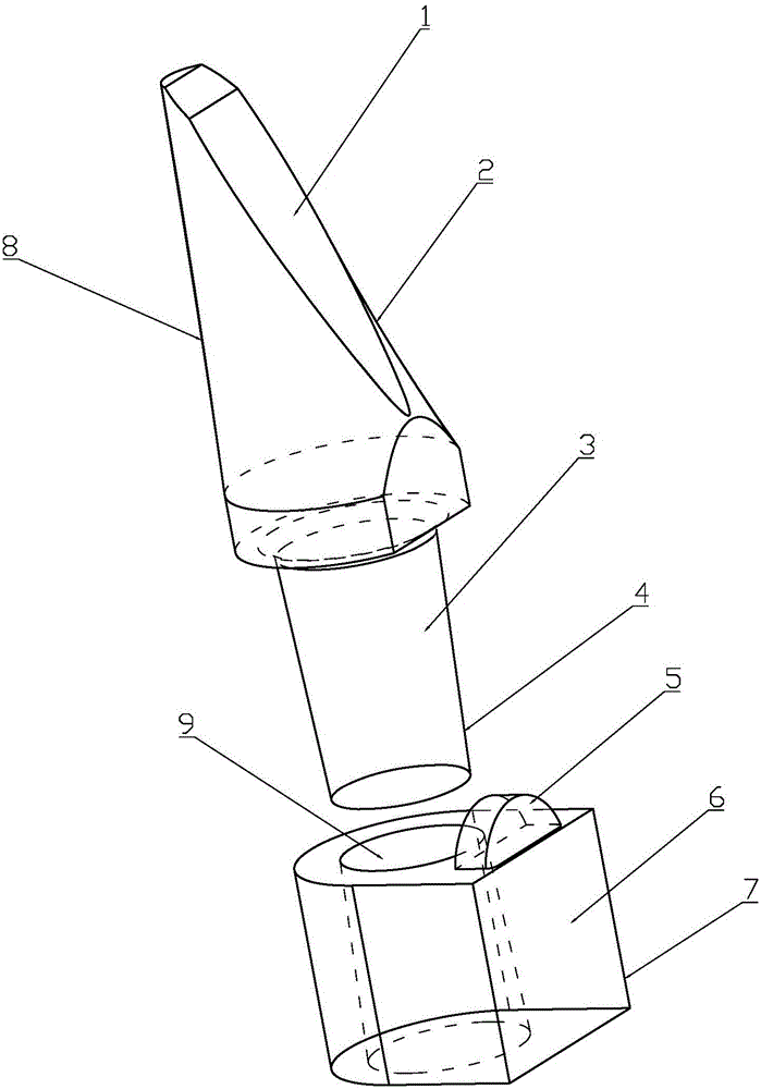
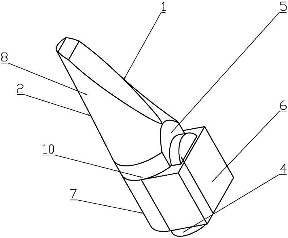
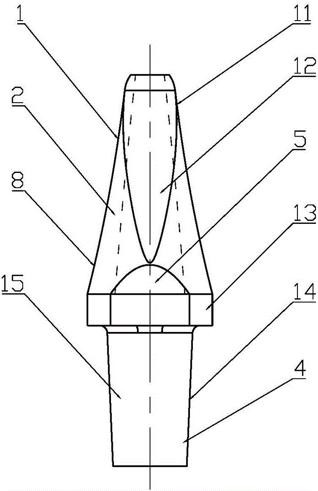
[0115] Figure 1 to Figure 17 The method for quickly installing and dismounting the reciprocating punching gear of the through-hole gear holder described in Embodiment 1 and the quick installation and dismounting of the reciprocating gear punching impact device for the through-hole gear holder, the rapid installation and disassembly of the through-hole gear holder includes a through hole Reciprocating tooth punching 1, reciprocating tooth punching through-hole seat 6, etc., the 6 holes of the reciprocating tooth punching through-hole seat are set in the same direction as the reciprocating punching tooth 1 reciprocating impact direction of the insertion hole, and the rear end of the reciprocating tooth punching 1 includes the insertion hole Hole reciprocating punching tooth handle 4 etc., inserting through hole reciprocating punching tooth handle 4 etc. is arranged on reciprocating punching tooth through hole seat 6 etc., as figure 1 and figure 2 As shown, the reciprocating p...

Embodiment 2

[0129] like Figure 18 and Figure 19 As shown, it is the reciprocating tooth punching impact device for quick installation and disassembly of the through hole gear seat shown in embodiment 2. The difference from embodiment 1 is that the reciprocating tooth punching impact device for quick installation and disassembly of the through hole tooth seat also includes a through hole for removal and insertion. The reciprocating gear puncher 40, the reciprocating impact power guide rod 41, the integrated block seal guide stop box 42, etc. The length of the reciprocating gear puncher 40 for unloading and inserting the through hole is the length of the reciprocating gear punching device 40 for unloading and inserting the through hole from the top tight integrated block seal. The length from the end of the guide anti-rotation box 42 to the rear end of the reciprocating punching handle 4 of the top-tight insertion hole is shorter than that of the rear end of the reciprocating punching too...

Embodiment 3

[0134] like Figure 20 and Figure 21 As shown, it is the quick installation and disassembly of the reciprocating punching gear impact device shown in Embodiment 3. The difference from Embodiment 1 is that the through-hole seat 7 of the oblique cone guide material anti-rotation gear includes a back-stop mechanism 46 and / or Anti-rotation structure 47 etc., such as Figure 20 Shown, oblique cone reciprocating guide material anti-rotation insertion through hole tooth 29 and oblique cone material anti-rotation gear through-hole seat 7 use through-hole reciprocating punching gear backstop 49 etc. to stop retreating, can also be oblique cone reciprocating guide material stop Turn and insert the through-hole tooth 29 and the oblique cone guide material anti-rotation tooth through-hole seat 7 to stop retreating 10 with the cone surface; for the anti-rotation structure 47 as Figure 20Shown, oblique cone reciprocating guide material anti-rotation insertion hole tooth 29 and oblique c...


PUM


Abstract

The invention belongs to the field of machinery and particularly relates to a method for rapidly assembling and disassembling a reciprocating impact tooth to a through hole tooth base and an impacting device with the through hole tooth base with the reciprocating impact tooth capable of being rapidly assembled and disassembled. The device comprises an insertion through hole reciprocating impact tooth, a reciprocating impact tooth through hole base, an insertion through hole reciprocating impact tooth handle, and the like. The insertion through hole reciprocating impact tooth handle is arranged in the reciprocating impact tooth through hole base, and is retained in a manner that the insertion through hole reciprocating impact tooth handle is retained against the reciprocating impact tooth through hole base via a tapered surface. A rotation-stopping device and the like are also arranged. The method and the device achieve rapid disassembly of the insertion through hole reciprocating impact tooth. The method and the device are practical and efficient, and expand the applications of a reciprocatingly impacting mining machine.

Description

technical field [0001] The invention relates to the field of mining machinery, in particular to a method for quickly installing and dismounting a through-hole tooth seat and a reciprocating tooth punching impact device for quickly installing and dismounting a through-hole tooth seat. Background technique [0002] Because the existing mining machines, rock drills and breakers do not have a structure that allows the reciprocating punch handle to be exposed to the rear of the reciprocating punch seat hole relative to the reciprocating impact power output end, the original reciprocating punch handles are all inserted into blind holes. The reciprocating tooth seat and the blind hole reciprocating tooth seat are fixed. In order to prevent the reciprocating tooth shank from falling off from the blind hole reciprocating tooth seat, a stopper is set at the junction of the reciprocating tooth shank and the blind hole reciprocating tooth seat. , due to the strong reaction force generat...

Claims


Application Information

Patent Timeline
IPC IPC(8): E21C25/02E21C35/18E21C35/183E21C35/08E21C35/00
CPCE21C25/02E21C25/04E21C25/68E21C31/02E21C35/00E21C35/08E21C35/18E21C35/183E21C35/187E21C35/19E21C35/20E21C35/22E21D9/106E21D9/1086E21D9/1093E21D9/12E21C25/00E21F13/00
Inventor 刘素华
Owner 刘素华
Learn More