
Horizontal well logging while drilling and ranging radar echo signal processing method

A technology of ranging radar and echo signals, which is applied in the direction of radio wave measurement systems, instruments, etc., can solve problems such as radar wave interference, failure to meet requirements, difficulty in identification, etc., and achieve reduced design difficulty, high processing accuracy, and good drilling The effect of encounter rate

Inactive Publication Date: 2016-09-28
CNPC DRILLING RES INST
View PDF9 Cites 0 Cited by
  • Summary
  • Abstract
  • Description
  • Claims
  • Application Information

AI Technical Summary

Problems solved by technology

At the same time, due to the inhomogeneity of the medium in the formation, the propagation process of the radar wave becomes very complicated, and the interference to the radar wave is also very serious, resulting in severe attenuation and distortion, so that the useful reflected wave signal is submerged in the noise , and difficult to identify
If only the weak radar reflection signal is detected and identified through the hardware circuit, it is far from meeting the requirements

Method used


Image

  • Horizontal well logging while drilling and ranging radar echo signal processing method
  • Horizontal well logging while drilling and ranging radar echo signal processing method
  • Horizontal well logging while drilling and ranging radar echo signal processing method

Examples


Embodiment Construction

[0017] Below, the implementation of the technical solution will be further described in detail in conjunction with the accompanying drawings.

[0018] Those skilled in the art can understand that although the following description involves many technical details related to the embodiments of the present invention, this is only an example for illustrating the principle of the present invention, and does not imply any limitation. The present invention can be applied to occasions other than the technical details exemplified below, as long as they do not deviate from the principle and spirit of the present invention.

[0019] In addition, in order to avoid making the description in this manual limited to redundant, in the description in this manual, some technical details that can be obtained in the existing technical documents may be omitted, simplified, modified, etc. understandable to human beings, and this does not affect the adequacy of the disclosure of this specification. ...


PUM


Abstract

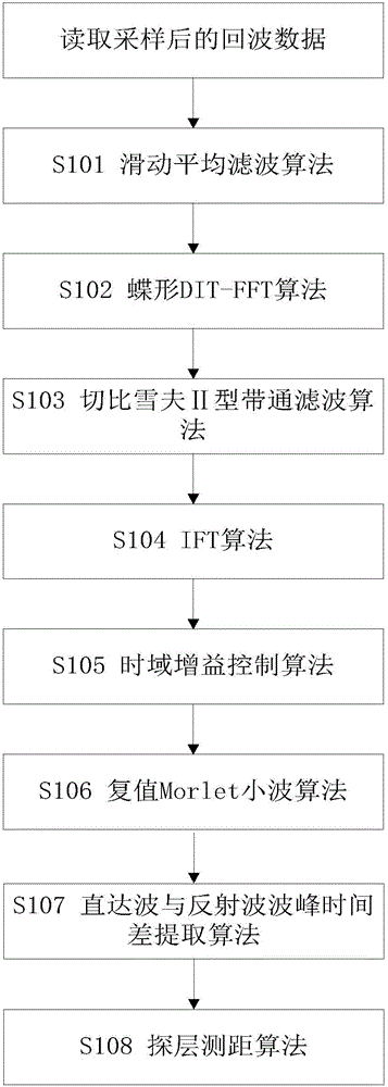
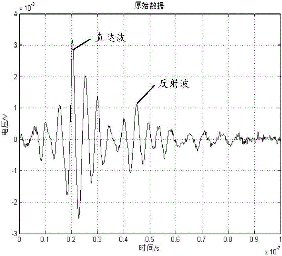
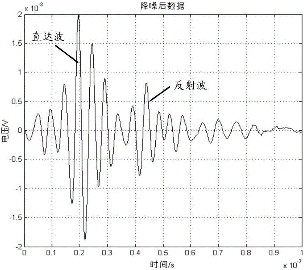
The present application discloses a method for processing radar echo signals of horizontal wells ranging with drilling, including the following steps: Step 1, performing sliding average filtering on the radar echo signals, wherein the radar echo signals include direct wave signal components and reflected wave signal components; step 2, carry out Fourier transform to the signal obtained in step 1, and convert it from time domain to frequency domain; step 3, carry out bandpass filtering to the signal; step 4, obtain step 3 Carry out inverse Fourier transform of the signal to convert it from the frequency domain to the time domain; step 5, amplify the reflected wave signal component in the signal obtained in step 4; step 6, for the signal obtained in step 5, obtain the The peak time difference between the direct wave signal component and the reflected wave signal component is used for layer detection and ranging.

Description

technical field [0001] The present invention relates to the field of oil and natural gas drilling, and in particular to a method for processing radar echo signals used in horizontal wells while drilling. The echo signal of the layer boundary is processed to obtain the key characteristic information of the weak reflected wave signal generated at the interface of the reservoir in the echo, and finally realize the boundary detection of the oil layer, coal seam, and other reservoirs. This technology is a horizontal well drilling while drilling One of the core technologies of layer ranging radar. Background technique [0002] With the continuous development of the petroleum industry and the increasing difficulty of oil and gas exploration and development, the oil exploration and development industry has gradually turned to the development of oil and gas reservoirs with small scale, thin oil and gas layers, poor physical properties and strong heterogeneity, directional wells, hori...

Claims


Application Information

Patent Timeline
IPC IPC(8): G01S7/41
CPCG01S7/41
Inventor 滕鑫淼盛利民王磊石荣弓志谦艾维平曹冲吕海川范锦辉
Owner CNPC DRILLING RES INST
Learn More