Snow depth measurement method based on image contrast

A measurement method and image comparison technology, which is applied in image enhancement, image analysis, and measurement devices, can solve problems such as large influence of temperature and wind speed, measurement errors, time-consuming and labor-intensive problems, and achieve the effect of improving accuracy and reducing the number of false alarms

Inactive Publication Date: 2016-09-28
BEIJING JIAOTONG UNIV +1
View PDF4 Cites 3 Cited by
  • Summary
  • Abstract
  • Description
  • Claims
  • Application Information

AI Technical Summary

Problems solved by technology

[0003] The traditional method is to use a snow measuring stick or a graduated snow measuring rod to be inserted into the snow to the ground surface to measure the snow depth on the ground. Because there is usually an ice layer under the snow, it is difficult to measure accurately with the snow measuring stick, and at the same time, the snow caused by wind blowing Snow is redistributed, so representative measurement points and multiple measurements need to be selected, this method is time-consuming and laborious, has large random errors, and is difficult to monitor in real time
[0004] At present, the existing snow depth measurement methods include radioisotope method, which has high accuracy but will endanger the health of surveyors; the measurement method based on image processing is greatly affected by weather and light, and its robustness is poor; the ultrasonic sensor snow depth measurement method, its It is greatly affected by temperature and wind speed, and the snow depth measurement method based on the phase method laser ranging principle has strong stability but is affected by the unevenness of the snow surface
Existing snow depth monitoring devices for high-speed railways are mainly based on the laser ranging method to measure snow depth. This measurement method requires that no obstructions are allowed on the laser measurement path, otherwise it will cause measurement errors
However, in the actual application environment of high-speed railway, it is inevitable that other objects enter the measurement area and block the snow depth measurement

Method used


Image

  • Snow depth measurement method based on image contrast

Examples


Embodiment Construction

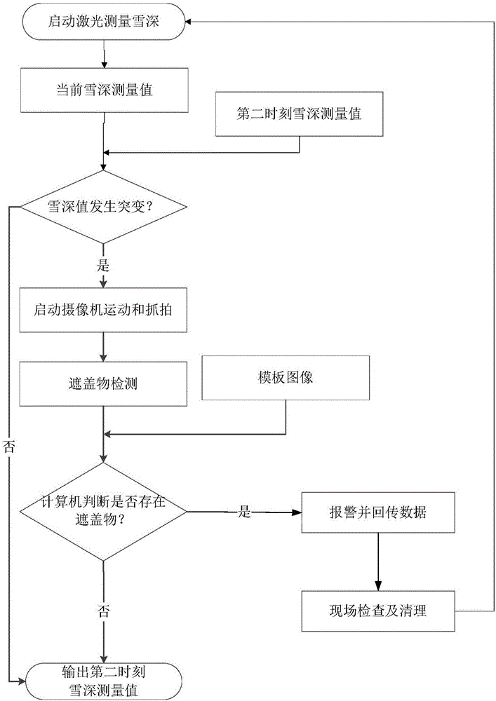
[0012] The method for detecting coverings based on image comparison in the present invention comprises the following steps:

[0013] (1) Start the laser to measure the snow depth, and record the current measurement value as the first measurement value;

[0014] (2) After 1 minute, start the laser again to measure the snow depth, and record the measured value as the second measured value;

[0015] (3) Compare the first measurement value with the second measurement value, if the difference between the two is greater than 5mm, it is determined that the measurement value has a sudden change, and enter step (4), if the difference between the two is less than the threshold value, then enter step (6);

[0016] (4) Determine whether there is a cover in the measurement area that causes a sudden change in the measurement value: start the camera movement and capture the measurement area, compare the captured measurement area image with the measurement area template image, and determine ...


PUM


Abstract

The invention provides a snow depth measurement method based on image contrast. In a condition in which an abrupt change happens when the snow depth value is measured by laser, a camera is started for capturing, whether the abrupt change is caused when a covering intrudes the measurement area is judged through an image contrast method, and if yes, a foreign object is eliminated. Through the detection method provided by the invention, interference to measurement of the snow depth value by the covering can be effectively eliminated, the calculation real-time performance is good, combination with the existing video monitoring system is facilitated, and the practical value is strong.

Description

technical field [0001] The invention relates to the field of meteorological observation and the field of snow depth monitoring of a high-speed rail disaster monitoring system, in particular to a method for measuring snow depth based on image comparison. Background technique [0002] With the rapid development of high-speed railways, the speed of trains is getting faster and faster. Therefore, the safety of trains has become the top priority of railway operations. Snowfall, as the severe weather condition that threatens the safety of railway trains, has great influence on the safe operation of railways. big influence. Snow accumulation will reduce the wheel-rail friction force and greatly increase the braking distance of the train, which will increase the probability of accidents and seriously threaten the safety of passengers' lives and property. Therefore, the real-time and accuracy of snow depth data is particularly important. [0003] The traditional method is to use a ...

Claims


Application Information

Patent Timeline
Patent Type & Authority Applications(China)
IPC IPC(8): G06T7/00G01W1/14
CPCG01W1/14G06T2207/10004Y02A90/10
Inventor 秦勇姚德臣刘洋程晓卿赵雪军付勇
Owner BEIJING JIAOTONG UNIV
Why Eureka
Try Eureka