Transformer coil

A technology of transformers and coils, applied in the direction of transformer/inductor coil/winding/connection, transformer/inductor components, inductor/transformer/magnet manufacturing, etc. Achieve the effect of increasing winding times, stable winding state, improving skin effect and heat dissipation performance

Inactive Publication Date: 2016-09-28
南通迪皮茜电子有限公司
View PDF6 Cites 0 Cited by
  • Summary
  • Abstract
  • Description
  • Claims
  • Application Information

AI Technical Summary

Problems solved by technology

[0006] In order to solve the above-mentioned problems, although an attempt was made to increase the efficiency of the transformer by increasing the number of windings of the circular cross-section aluminum coil wires, as described above, since the wound coil wires are in line contact with each other, many vacant spaces are formed, which causes It will not only reduce the efficiency of the transformer, but also increase the size and weight of the transformer

Method used


Image

  • Transformer coil
  • Transformer coil
  • Transformer coil

Examples


Embodiment Construction

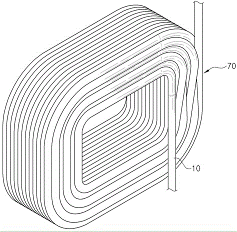
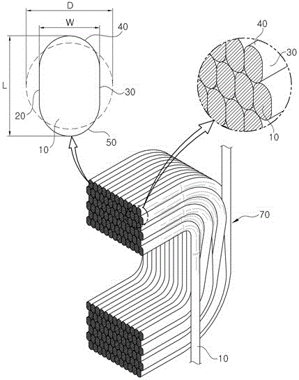
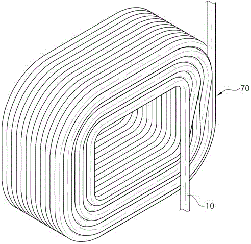
[0027] figure 1 It is a perspective view of a transformer coil applicable to an embodiment of the present invention (D:W=1:0.89, D:L=1:1.03), figure 2 Yes figure 1 cross-sectional oblique view of image 3 It is a perspective view of a coil for a transformer applicable to another embodiment of the present invention (D:W=1:0.79, D:L=1:1.04), Figure 4 Yes image 3 cross-sectional oblique view.

[0028] like figure 1 arrive figure 2 As shown, the coil for a transformer in a preferred embodiment of the present invention, wherein the coil for a transformer formed by winding a coil wire is characterized in that: the above-mentioned coil wire 10 with a specific diameter D and a circular cross-section is tightly wound from left to right, wherein the above-mentioned coil The left side 20 and the right side 30 of the wire 10 are flat up and down, the upper side 40 of the above-mentioned coil wire 10 is circularly convex upward, and the lower side 50 of the above-mentioned coil ...


PUM


Abstract

The invention relates to a transformer coil; winding coil wires can form mutual surface contacts, thus using less winding frequency to improve transformer efficiency; the coil wire can be winded to form the transformer coil; a specific diameter D is formed, and coil wires (10) on the round cross section can left-right tightly wind; the left side face (20) and right side face (30) of the coil wire (10) are flat on top and bottom; the top side face (40) of the coil wire (10) protrudes upwards in a round shape; the bottom side face (50) of the coil wire (10) protrudes downwards in a round shape, so the left and right side faces of the coil wire (10) can form surface contacts; the length W from the left side face (20) to the right side face (30) and the diameter D are arranged according to the ratio of 1: 0.7-0.95; the maximum length L from the top side face (40) to the bottom side face (50) and the diameter are arranged according to the ratio of 1: 1.01-1.25.

Description

technical field [0001] The present invention relates to a coil for a transformer formed by winding coil wires, in particular, a coil wire with a specific diameter and a circular cross-section is tightly wound left and right, wherein the left side and right side of the coil wire are flat up and down 1. The upper side of the above-mentioned coil wire has an upward circular protrusion, and the lower side of the above-mentioned coil wire has a downward circular protrusion, so that when the coil wire is wound, the left and right sides form surface contact with each other, so that the coil can be lifted with fewer winding times. The transformer uses a coil for its transformer efficiency. Background technique [0002] Conventional coils for transformers use coil wires with a circular cross-section. Therefore, even if the coil wires are in contact with each other during winding, there are many empty spaces, which reduces the efficiency of the transformer accordingly. [0003] The o...

Claims


Application Information

Patent Timeline
Patent Type & Authority Applications(China)
IPC IPC(8): H01F41/066H01F41/074H01F27/28
CPCH01F27/2871
Inventor 安胜英龚樊昌
Owner 南通迪皮茜电子有限公司
Why Eureka
Try Eureka