U-shaped beam forming machine with rack type blank centring devices

A centering device and rack-type technology, applied in the field of U-shaped beam forming machines, can solve the problems of high cost, high labor intensity, and different plate thicknesses, etc., and achieve ingenious connection technology, flexible rolling, and fast forming speed. Effect

Inactive Publication Date: 2016-10-05
林晓强
View PDF7 Cites 1 Cited by
  • Summary
  • Abstract
  • Description
  • Claims
  • Application Information

AI Technical Summary

Problems solved by technology

[0002] like figure 1 As shown, a U-shaped channel steel beam (abbreviated as U-shaped beam) is an important part in the manufacture of the scale platform of the existing truck scale, and is the main load-bearing beam in the scale platform structure. These U-shaped beams of different quantities and strengths are welded to form a weighing platform; according to different loads, these U-shaped beams have different heights and lengths, some have different thicknesses, and some have different widths; at present, weighing apparatus manufacturers mainly use U-shaped beams. The specification of shaped beams is U-shaped beams with different heights and lengths according to different tonnages. The height is generally 250mm to 500mm, the length is generally 4m to 9m, and the width varies from manufacturer to manufacturer, generally 200mm to 300mm. U-shaped beams are commonly used by each manufacturer. The width is generally the same, and some products use U-shaped beams of different widths; the existing weighing apparatus manufacturers process these U-shaped beams by manually lifting the strip steel (the blank is strip steel) on the bending machine (a standard machine tool). The folded one needs to be bent repeatedly to form it; the longer one of the commonly used U-shaped beams weighs about 400kg, and requires five to six strong labors to operate. Generally, U-shaped beams also need 3 to 4 workers to operate. The labor intensity is high, and the cost is high due to the large number of people; many manufacturers have to change long beams into multi-section short beams and then weld them together, resulting in low efficiency and poor quality

Method used


Image

  • U-shaped beam forming machine with rack type blank centring devices
  • U-shaped beam forming machine with rack type blank centring devices
  • U-shaped beam forming machine with rack type blank centring devices

Examples


specific Embodiment approach

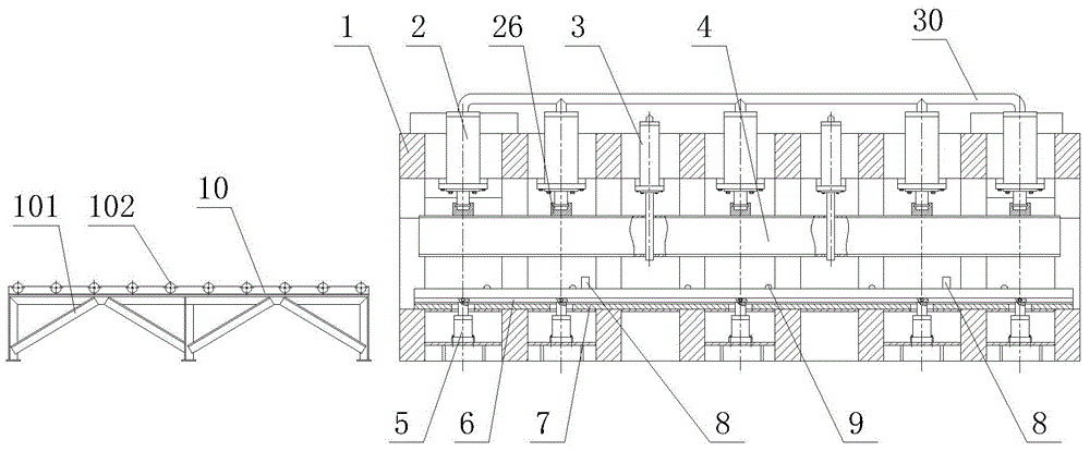
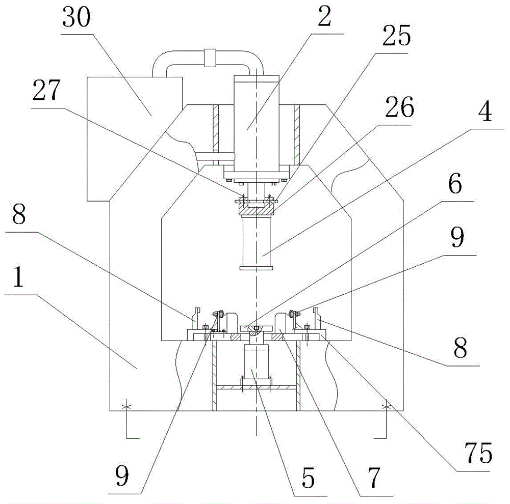
[0031] Such as figure 2 , image 3 As shown, a U-shaped beam forming machine with a rack-type blank centering device includes a frame 1, a bending cylinder 2, an upper mold 4, a lower mold 7, an upper demoulding cylinder 3, a lower demoulding cylinder 5, Hydraulic system 30, rack-type blank centering device 8, booster device 9 and front platform 10, the cylinder bodies of the multiple bending cylinders 2 are connected to the upper beam of the frame 1; the bending cylinders 2 The piston rod is connected with the upper mold 4 through the piston connection seat 26, the insert pin 25, and the bolt 27; The piston rod of the oil cylinder 3 can pass through the inside of the upper mold 4 during telescopic activities. After the upper mold 4 is ejected, if the U-shaped beam can clamp the upper mold 4, the upper demoulding cylinder 3 is started at this time, and the piston rod of the upper demoulding cylinder is extended. The U-shaped beam will be pushed down to solve the problem of ...


PUM


Abstract

The invention discloses a U-shaped beam forming machine with a rack-type billet centering device, which includes a frame, a bending cylinder, an upper mold, a lower mold, an upper demoulding cylinder, a lower demoulding cylinder, a hydraulic system, and a rack The blank centering device, the booster device and the front platform of the machine, the cylinder body of the bending cylinder is connected to the frame; the piston rod of the bending cylinder is connected to the upper mold; the upper demoulding cylinder is connected to the frame, and the upper The piston rod of the demoulding oil cylinder can be passed down from the inside of the upper mold when it moves; the lower mold is connected with the frame through an L-shaped pressure plate and bolts; the back seat of the lower demoulding oil cylinder is connected in the lower box beam of the frame, It is connected with the stripping plate; the booster device is connected to the lower mold; the rack type billet centering device is connected to the lower box beam of the frame; the hydraulic system is set on the upper part of the frame or can be set independently on the frame Nearby, each working oil cylinder is connected through an oil circuit; the front platform is arranged in front of the feed port of the frame.

Description

technical field [0001] The invention belongs to the field of mechanical processing and manufacturing equipment, and in particular relates to a special equipment for weighing apparatus production, that is, a U-shaped beam forming machine. Background technique [0002] Such as figure 1 As shown, a U-shaped channel steel beam (abbreviated as U-shaped beam) is an important part in the manufacture of the scale platform of the existing truck scale, and is the main load-bearing beam in the scale platform structure. These U-shaped beams of different quantities and strengths are welded to form a weighing platform; according to different loads, these U-shaped beams have different heights and lengths, some have different thicknesses, and some have different widths; at present, weighing apparatus manufacturers mainly use U-shaped beams. The specification of shaped beams is U-shaped beams with different heights and lengths according to different tonnages. The height is generally 250mm t...

Claims


Application Information

Patent Timeline
Patent Type & Authority Applications(China)
IPC IPC(8): B21D5/06B21D43/00B21D37/10B21D45/04
Inventor 林晓强
Owner 林晓强
Why Eureka
Try Eureka