Method of attaching ring gear to differential case, jig, and differential case

A technology for differential case and ring gear, which is applied in differential transmission, manufacturing tools, household appliances, etc. It can solve problems such as cracks on the inner peripheral surface of the riveted fixed part, and achieve the effect of preventing cracks

Inactive Publication Date: 2016-10-05
TOYOTA JIDOSHA KK
View PDF9 Cites 2 Cited by
  • Summary
  • Abstract
  • Description
  • Claims
  • Application Information

AI Technical Summary

Problems solved by technology

[0003] However, when the riveted fixing portion of the differential case is deformed outward, tensile stress is generated in the inner peripheral surface of the riveted fixing portion, and due to this tensile stress, cracks are generated in the inner peripheral surface of the riveted fixing portion

Method used


Image

  • Method of attaching ring gear to differential case, jig, and differential case
  • Method of attaching ring gear to differential case, jig, and differential case
  • Method of attaching ring gear to differential case, jig, and differential case

Examples


no. 1 approach

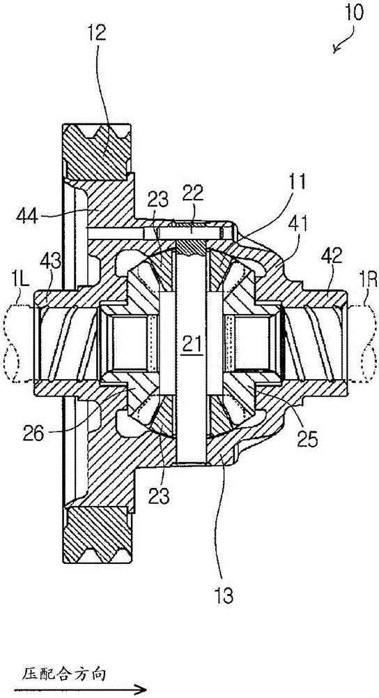
[0045] In the following, reference will be made to Figure 1 to Figure 11 The first embodiment will be described. Such as figure 1 As shown in , the differential 10 includes a differential mechanism 11 , a differential case 13 and a ring gear 12 , wherein the differential case 13 accommodates the differential mechanism 11 and the ring gear 12 is joined to the differential case 13 . The differential 10 transmits the power input to the differential 10 from the engine to the right drive wheel and the left drive wheel via the ring gear 12 . In addition, this differential 10 allows right and left drive wheels to rotate at rotational speeds different from each other through a differential mechanism 11 .

[0046] The differential mechanism 11 includes a pinion shaft 21 , a fixed pin 22 and a pair of pinion gears 23 . The pinion shaft 21 is supported by the differential case 13 . The fixing pin 22 fixes the pinion shaft 21 to the differential case 13 . A pair of pinion gears 23 a...


PUM


Abstract

A method of attaching a ring gear to a differential case, a jig, and the differential case are provided. The method of attaching the ring gear (12) to the differential case (13) includes: a first step for fitting the ring gear (12) onto an outer peripheral side of the differential case (13); and a second step for outwardly deforming a caulk-fixed part (52) of the differential case (13) to prevent the ring gear (12) from being dropped out from the differential case (13). In the second step, the jig (60) having an inclined surface (61) that can contact an inner peripheral surface (53) of the caulk-fixed part (52) of the differential case (13) is pushed along a rotational axis direction of the differential case (13) to outwardly deform the caulk-fixed part (52). The inclined surface (61) of the jig (60) and the inner peripheral surface (53) of the caulk-fixed part (52) are subjected to a surface treatment to increase a friction between the inclined surface (61) of the jig (60) and the inner peripheral surface (53) of the caulk-fixed part (52).

Description

technical field [0001] The present invention relates to a method of attaching a ring gear to a differential case, a jig and a differential case for attachment. Background technique [0002] International Patent Application Publication WO.2012 / 004866 discloses a method of fitting a ring gear to the outer peripheral side of a differential case and then deforming the riveted fixing portion of the differential case outward so as to prevent the ring gear from dislodging from the differential case. Shedding technology. Specifically, to outwardly deform the caulked fixing portion of the differential case, a jig having an inclined surface capable of contacting the inner peripheral surface of the caulked fixing portion is pushed in the axial direction of the ring gear. [0003] However, when the rivet fixing portion of the differential case is deformed outward, tensile stress is generated in the inner peripheral surface of the rivet fixing portion, and cracks are generated in the in...

Claims


Application Information

Patent Timeline
Patent Type & Authority Applications(China)
IPC IPC(8): B21K25/00B21K21/12B23P11/00F16H48/40
CPCB21K21/12B21K25/00B23P11/005F16H48/40F16H2048/382F16H2048/385F16H48/08F16H48/38
Inventor 石原弘章
Owner TOYOTA JIDOSHA KK
Why Eureka
Try Eureka