Thermal deformation compensation mechanism and method for ram main shaft of boring and milling machine

A compensation mechanism, thermal deformation technology, applied in other manufacturing equipment/tools, manufacturing tools, etc., can solve problems that affect the processing accuracy of parts, damage accuracy, etc.

Inactive Publication Date: 2016-10-05
SHENJI GRP KUNMING MACHINE TOOL
View PDF7 Cites 7 Cited by
  • Summary
  • Abstract
  • Description
  • Claims
  • Application Information

AI Technical Summary

Problems solved by technology

For boring and milling machines, thermal displacements of different amplitudes of components of the ram spindle milling head are caused, which in turn causes thermal deformation of various rams such as tension, compression, bending, and twisting, so as to change t

Method used


Image

  • Thermal deformation compensation mechanism and method for ram main shaft of boring and milling machine
  • Thermal deformation compensation mechanism and method for ram main shaft of boring and milling machine
  • Thermal deformation compensation mechanism and method for ram main shaft of boring and milling machine

Examples


Embodiment Construction

[0047] In order to make the purpose, technical solution and advantages of the invention clearer, the invention will be further described in detail below in conjunction with the accompanying drawings and specific embodiments. Although exemplary embodiments of the present disclosure are shown in the drawings, it should be understood that the invention may be embodied in various forms and should not be limited to the embodiments set forth herein. Rather, these embodiments are provided for more thorough understanding of the present invention and to fully convey the scope of the present invention to those skilled in the art.

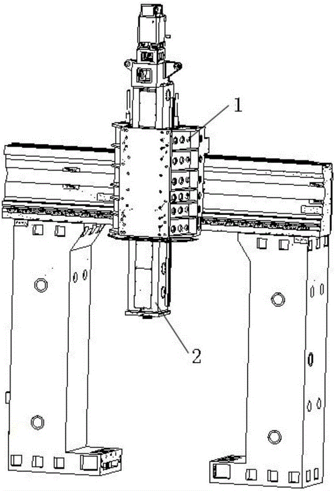
[0048] figure 1 It shows a schematic structural view of the gantry frame of a boring and milling machine according to an embodiment of the present invention. The beam of the gantry of the boring and milling machine is provided with a slide plate 1, a ram 2 arranged on the slide plate 1 and capable of moving along its slide rail, The boring and milling machin...


PUM

PropertyMeasurementUnit
Coefficient of linear thermal expansionaaaaaaaaaa

Abstract

The present application provides a thermal deformation compensation mechanism for the ram spindle of a boring and milling machine, which includes a grating scale displacement sensor fixedly arranged on the inner wall of the slide plate; a thermal standard element fixedly arranged in the ram; The grating scale line displacement reading head that is fixedly connected with the thermal standard element; when the grating scale line displacement reading head moves under the drive of the thermal standard element to generate readings, the control system can according to the The readout controls the ram to perform compensating motion. The present application provides a thermal deformation compensation mechanism and method to transfer the thermal elongation deformation of the front end of the ram to the linear displacement reading head of the grating ruler. The linear displacement reading head of the grating scale and the displacement sensor of the grating scale generate the movement value and feed it back to the control system, so that the control system can control the servo motor to adjust the position of the ram, and realize the compensation for the thermal deformation of the main shaft of the ram.

Description

technical field [0001] The invention and the field of numerically controlled machine tools particularly relate to a thermal deformation compensation mechanism and a compensation method for a thermally deformed main shaft of a ram main shaft of a boring and milling machine. Background technique [0002] At present, the factors affecting the machining accuracy of CNC machine tools can be summarized into four categories: geometric errors of the main mechanical structure of machine tools; load errors during processing; thermal deformation errors; servo system control errors. A large number of studies have shown that thermal deformation in precision machining has become a key factor affecting the stability of machining accuracy, and the machining error caused by it accounts for as high as 40% to 70% of the total error. [0003] CNC machine tools are affected by various heat sources such as frictional heat, cutting heat, and room temperature changes during the working process. The...

Claims


Application Information

Patent Timeline
IPC IPC(8): B23Q23/00
CPCB23Q23/00
Inventor 刘啸李波波李绍萍彭梁锋王元伦张文坤张楠李攀科夏跃荣尹亮杨林谭丽娟田刘平
Owner SHENJI GRP KUNMING MACHINE TOOL
Why Eureka
Try Eureka