
Eureka
For R&D, Eureka makes reading and utilizing patents & technical documents easy.
Eureka AIR
Designed for self-driven R&D workflows. Generate viable solutions, solve complex R&D challenges, empower your innovation with AI.

Eureka Materials
Designed for material experts only. Revolutionize your material R&D, from search, analyze, to developing new materials.

TechResearch
Generate reliable direction feasibility study reports for your R&D in just a few steps.

TechSeek
Discover and master advanced knowledge NOW. Basics, ideas, possibilities, all at once.

TechMind
As an expert in R&D Theories, TechMind can generates customized viable solutions instantly.

TechRisk
Analyze your overall solution with one click, know your potential R&D risks in advance.

TechMonitor
Get weekly tech updates, stay abreast of the latest tech innovations and key insights.
Method of controlling injection molding machine manipulator, the injection molding machine manipulator, and driver thereof
A technology of injection molding machines and manipulators, applied in the field of manipulators, can solve the problems of large space occupation and heavy weight of the drive system
- Summary
- Abstract
- Description
- Claims
- Application Information
AI Technical Summary
Problems solved by technology
Method used
Image

Examples
Embodiment 1
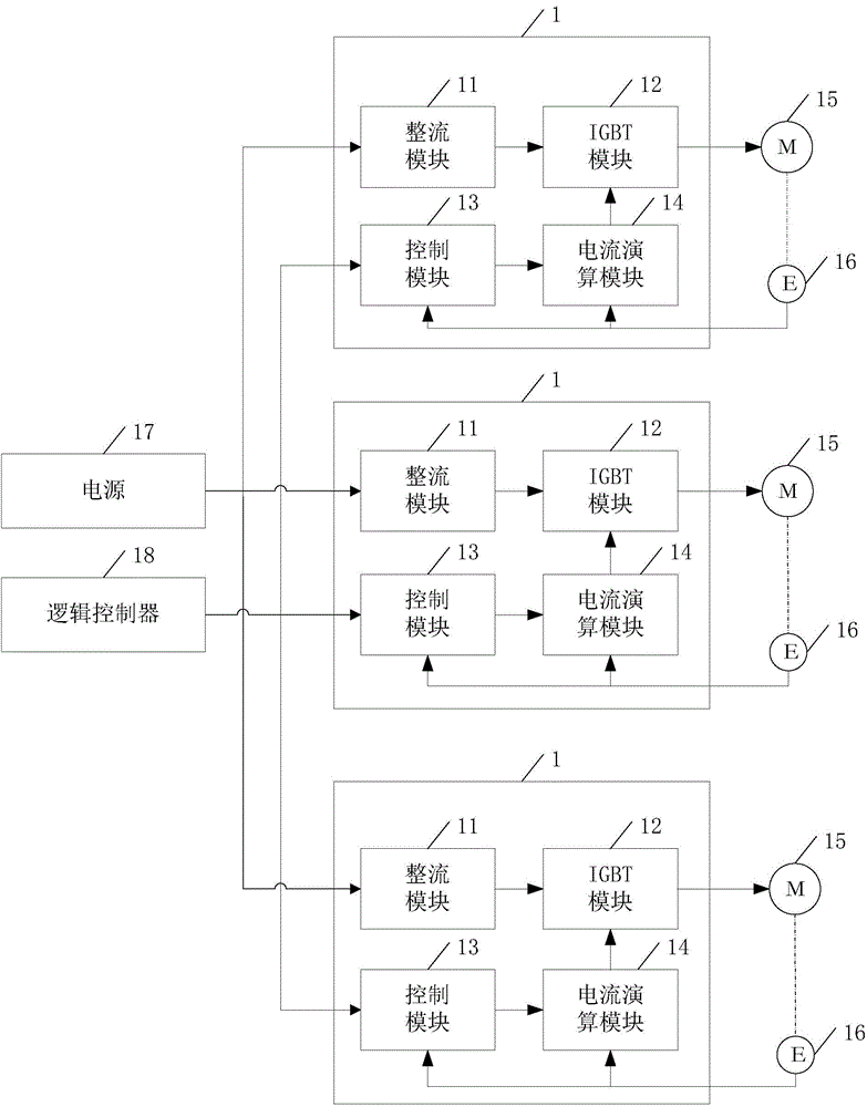
[0046] The driver is used for injection molding machine manipulator, including rectification module, insulated gate bipolar transistor IGBT module, current calculation module and control module.
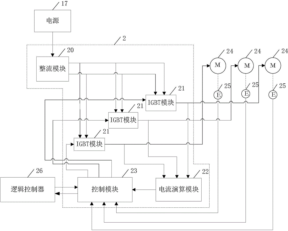
[0047] The number of the rectification module, the current calculation module and the control module is one, and the number of the insulated gate bipolar transistor IGBT modules is N;
[0048] The output terminal of the rectification module is connected to the first input terminals of the N IGBT modules, so as to transmit electric energy to each of the IGBT modules;
[0049] The output terminals of each of the insulated gate bipolar transistor IGBT modules are connected to the input terminals of the current calculation module, and connected to the motors of the respective motion axes of the manipulator of the injection molding machine in one-to-one correspondence;
[0050] The first input end of the control module is connected to the output end of the current calculation module; the ...
Embodiment 2
[0065] An injection molding machine manipulator, including: N motion axes, a motor, an encoder, a logic controller, and the driver described in Embodiment 1;
[0066] Each of the motion axes is provided with a motor and an encoder for collecting the actual rotational speed of the motor;
[0067] The logic controller is communicatively connected with the control module of the driver.
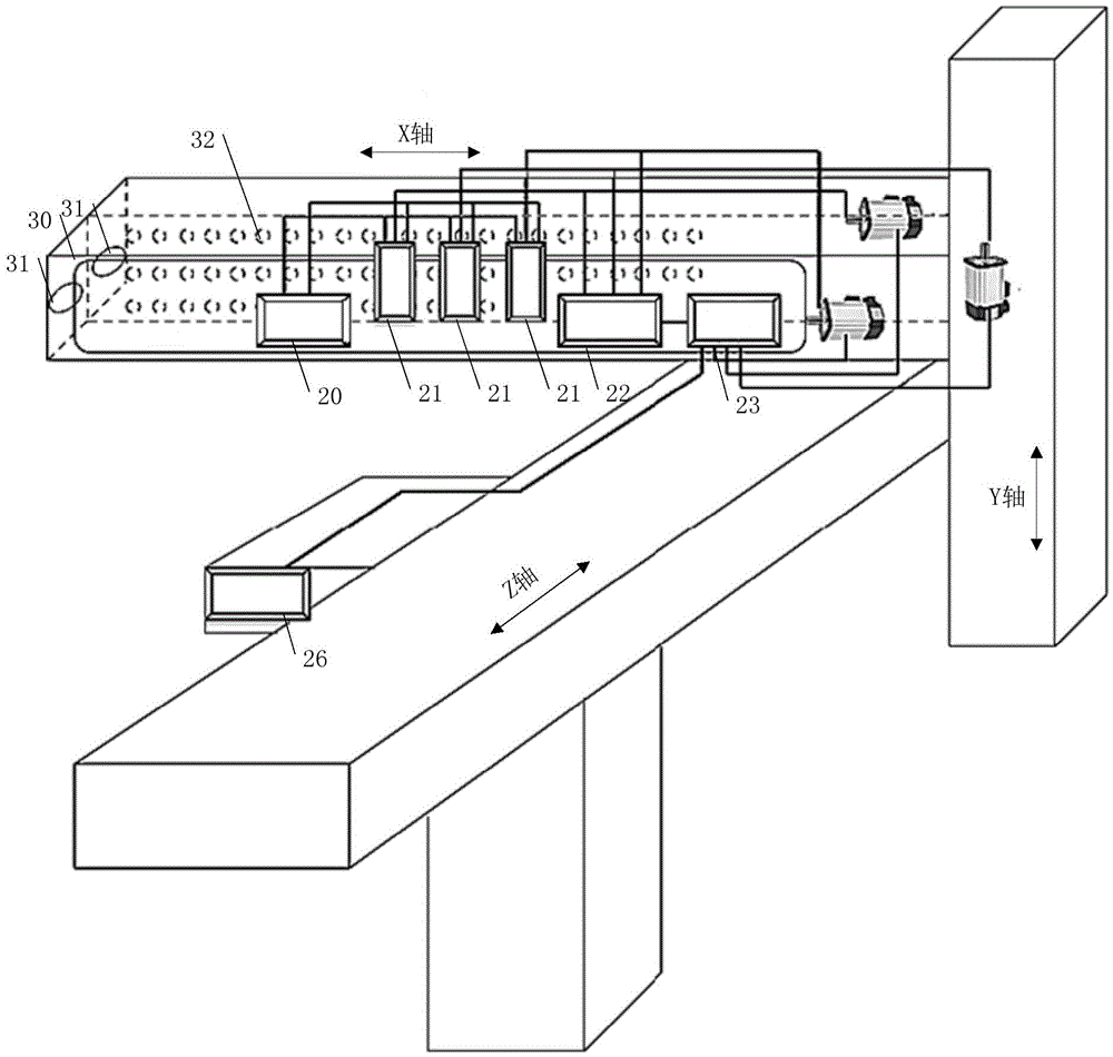
[0068] Such as figure 2 As shown, since the specific structure of the driver 2 has been described in detail in the first embodiment, it will not be repeated here. Each motor 24 and encoder 25 are arranged on each motion axis, and the control module 23 and the logic controller 26 are connected in communication, that is, the control module 23 transmits the analysis and processing of the actual rotational speed and theoretical rotational speed collected by the encoder 25 to the logic controller 26 . After receiving the data from the control module 23 , the logic controller 26 judges the next act...
Embodiment 3
[0094] A method of controlling an injection molding machine manipulator, comprising:
[0095] S10: the rectifier module transmits electric energy to each IGBT module electrically connected to it;
[0096] S11: the logic controller sends corresponding instructions to the control module in the driver according to the current movement of each movement axis of the manipulator of the injection molding machine;
[0097] S12: The control module sends the instruction to a corresponding IGBT module;
[0098] S13: the insulated gate bipolar transistor IGBT module controls the speed of the motor connected to it according to the instruction;
[0099] S14: Each encoder collects the actual speed of the motor connected to it, and feeds back the actual speed to the control module;
[0100] S15: The current calculation module obtains the theoretical rotational speed of each of the motors, and feeds back the theoretical rotational speed to the control module;
[0101] S16: The control module a...
PUM
 Abstract
Description
Claims
Application Information
 - R&D Engineer
- R&D Manager
- IP Professional
- Industry Leading Data Capabilities
- Powerful AI technology
- Patent DNA Extraction
Browse by: Latest US Patents, China's latest patents, Technical Efficacy Thesaurus, Application Domain, Technology Topic, Popular Technical Reports.
© 2024 PatSnap. All rights reserved.Legal|Privacy policy|Modern Slavery Act Transparency Statement|Sitemap|About US| Contact US: help@patsnap.com