
Spring support, mover assembly, pump body structure and compressor

A technology of supports and components, applied in the field of compressors, can solve problems such as deformation of spring supports, achieve the effects of reducing friction, ensuring the performance of the whole machine, and reducing processing costs

Active Publication Date: 2018-11-13
GREE ELECTRIC APPLIANCES INC
View PDF10 Cites 0 Cited by
  • Summary
  • Abstract
  • Description
  • Claims
  • Application Information

AI Technical Summary

Problems solved by technology

[0005] Based on this, it is necessary to address the problem that the bending part of the spring support is easily deformed during the operation of the compressor, and to provide a spring support that can reduce the deformation, the mover assembly containing the spring support, and the mover The pump body structure of the assembly, and the compressor containing the pump body structure

Method used


Image

  • Spring support, mover assembly, pump body structure and compressor
  • Spring support, mover assembly, pump body structure and compressor
  • Spring support, mover assembly, pump body structure and compressor

Examples


Embodiment Construction

[0054]In order to make the purpose, technical solution and advantages of the present invention clearer, the spring support member, the mover assembly, the pump body structure and the compressor of the present invention will be further described in detail through the following embodiments in conjunction with the accompanying drawings. It should be understood that the specific embodiments described here are only used to explain the present invention, not to limit the present invention.

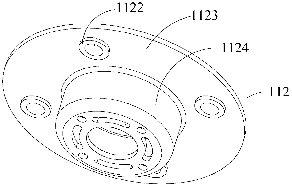
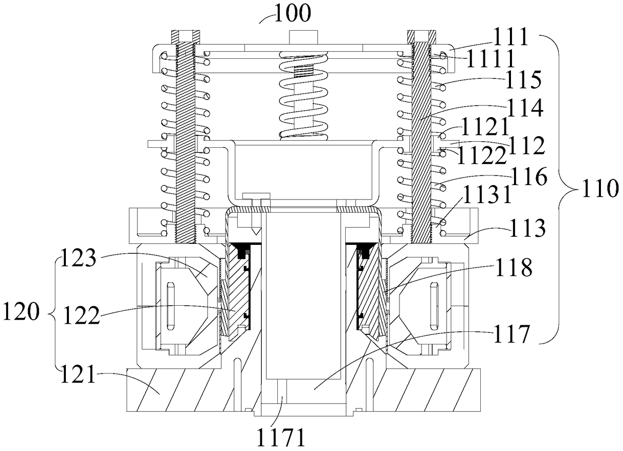
[0055] see Figure 1 to Figure 3 The spring support member 112 in one embodiment of the present invention includes a cylinder body 1124 and an end plate 1123, the end plate 1123 is a flat plate structure, the cylinder body 1124 is a hollow cylindrical structure, and one end of the cylinder body 1124 is arranged on the end plate 1123, The other end of the barrel 1124 is connected with the piston 117 . A connection hole is provided on the cylinder body 1124 , through which the connecting piece co...


PUM


Abstract

The invention provides a spring supporting part, a rotor assembly, a pump body structure and a compressor. The spring supporting part comprises a barrel body and an end plate, wherein the end plate is in a flat-plate-shaped structure; the barrel body is of a hollow cylindrical structure; one end of the barrel body is arranged on the end plate; the end plate is provided with a through hole; a first lug boss and a second lug boss are arranged at the two ends of the through hole respectively; and the central line of the first lug boss is overlapped with the central line of the second lug boss at the corresponding position, so that the deformation of the spring supporting part is reduced, and an eccentric wearing phenomenon of a piston and an air cylinder is prevented.

Description

technical field [0001] The invention relates to the field of compression equipment, in particular to a spring support for support, a mover assembly including the spring support, a pump body structure including the mover assembly, and a compressor including the pump body structure. Background technique [0002] Currently, reciprocating compressors all have a part like a crankshaft, which is used to convert the rotational torque of the motor into the driving force for the reciprocating motion of the piston. This conversion of motion results in significant mechanical friction losses in the reciprocating compressor. In order to solve the problem of large mechanical friction loss, the industry has targeted linear compressors. The linear compressor cancels the crankshaft of the rotary compressor, and the piston reciprocates in the cylinder driven by the linear motor to complete the compression of the refrigerant. Since the parts of the linear compressor are reduced, the structur...

Claims


Application Information

Patent Timeline
Patent Type & Authority Patents(China)
IPC IPC(8): F16F1/12F16F15/123F04B53/00
Inventor 黄传顺崔中刘成胡余生魏会军
Owner GREE ELECTRIC APPLIANCES INC
Learn More