

Fixing device and image forming device
An image and clamping part technology, applied to the electric recording process using the charge pattern, equipment and instruments using the charge pattern electric recording process, etc., can solve the problems of increased power consumption, heat loss, and time increase of the fixing device. Achieve the effect of reducing power consumption and shortening warm-up time
- Summary
- Abstract
- Description
- Claims
- Application Information
AI Technical Summary
Problems solved by technology
Method used
Image

Examples
no. 1 approach
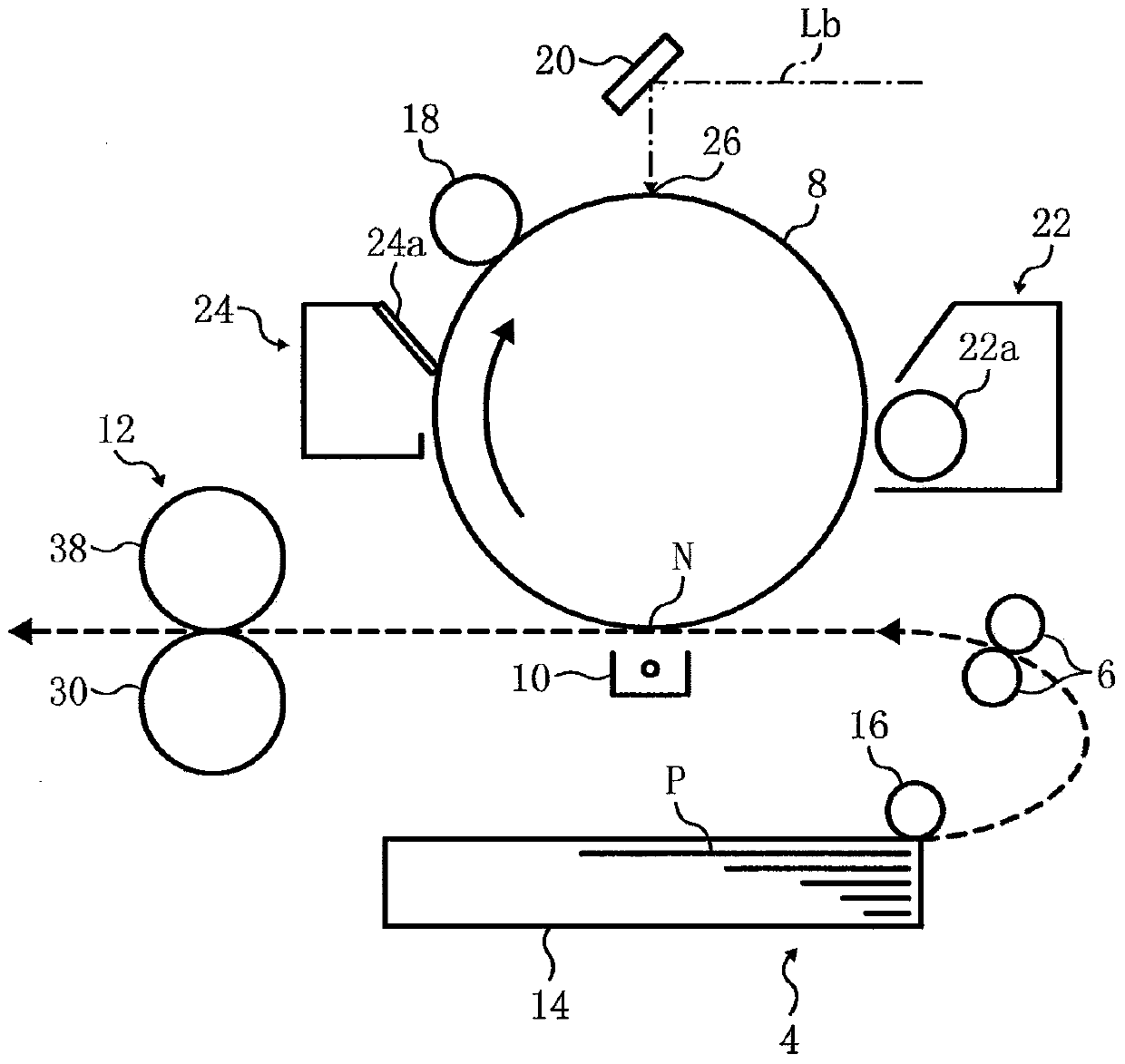
[0026] figure 1 Shown is a schematic diagram of a monochrome printer of an image forming apparatus according to an embodiment of the present invention. The present invention is similarly applicable to known color image forming apparatuses.
[0027] Such as figure 1 As shown, the black and white printer includes a photoreceptor 8 as an image carrier, a charging roller 18 as a charging mechanism, a mirror 20 as an exposure mechanism, a developing device 22 with a developing roller 22a as a developing mechanism, and a transfer device 10 . In addition, the black and white printer also includes a cleaning device 24 having a cleaning blade 24a.
[0028] Between the charging roller 18 and the developing device 22 , the exposure light Lb is irradiated to the exposure portion 26 on the photoreceptor 8 through the mirror 20 and scanned. A paper feed mechanism 4 is arranged at the lower part of the printer, and a registration roller pair 6 is provided in the middle of a paper conveyan...
no. 2 approach
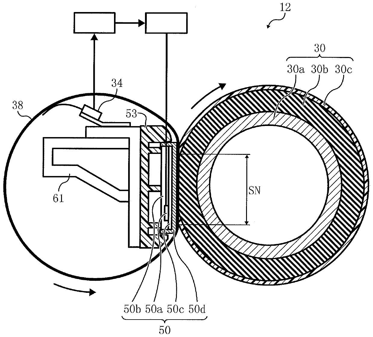
[0059] Figure 5 Shown is an enlarged schematic view of a fixing nip portion of a fixing device according to a second embodiment. exist Figure 5 in, with Figure 4 The same components are assigned the same symbols, and detailed descriptions thereof are omitted.
[0060] The fixing device 12 according to this embodiment is different from the fixing device 12 according to the first embodiment in the shape of the heating member 50 . That is, the heat conduction member 50 dS is inclined or protrudes on the side of the pressure roller 30 from upstream toward the downstream portion in the recording material conveyance direction at the fixing nip SN. Thus, the pressure acting in the fixing nip SN is greater at the outlet than at the nip inlet.
[0061] Image 6 Shown is the pressure profile of the fixing nip. In the figure, the horizontal axis represents the position in the recording material conveyance direction of the fixing nip SN, and the vertical axis represents the surfa...
no. 3 approach
[0071] Figure 10 Shown is an enlarged schematic view of a fixing nip portion of a fixing device according to a third embodiment. exist Figure 10 in, with Figure 4 The same components are assigned the same symbols, and detailed descriptions thereof are omitted.
[0072] Such as Figure 10 As shown, the width of the heat conduction member 50 dW of the fixing device according to the present embodiment in the recording material conveyance direction is larger than that of the fixing nip SN. Then, the heat-resistance layer 50 a is arranged in the thermally conductive member 50 dW at the upstream portion in the recording material conveyance direction from the fixing nip SN. Therefore, the fixing belt 38 can be heated from before the fixing nip SN, and even if the fixing belt 38 moves at a high speed, sufficient heat can be transferred to the recording material in the fixing nip SN. Therefore, while the fixing nip SN is pressurized by the heating member 50, the heat transfer e...
PUM
 Abstract
Description
Claims
Application Information