Display touch apparatus

A technology of touch devices and touch components, applied in optics, instruments, electrical digital data processing, etc., can solve problems such as high reflectivity and inability to clearly identify content

Active Publication Date: 2016-10-05
TPK TOUCH SOLUTIONS (XIAMEN) INC
View PDF4 Cites 5 Cited by
  • Summary
  • Abstract
  • Description
  • Claims
  • Application Information

AI Technical Summary

Problems solved by technology

However, the actual measurement of existing devices shows that their reflectivity is high (>2.5%)
Excessively high reflectivity

Method used


Image

  • Display touch apparatus
  • Display touch apparatus
  • Display touch apparatus

Examples


Embodiment 1

[0035] Take five groups of LCDs and measure their glare value to be 111. After laminating the anti-glare film (fogged PET) to five groups of LCDs, the glare values ​​were measured, and the glare values ​​were 79.8, 74.6, 64.6, 79.9, and 75.3. The LCD with the anti-glare film attached thereto has a lower glare value than the LCD without the anti-glare film attached.

Embodiment 2

[0037] Take three groups of LCDs and measure their optical reflection properties (the measurement standard is MFS-630, and the light incident angle is 8°), as shown in Table 1. The light reflection diagram of the above LCD is shown in Figure 4 shown.

[0038] Take the same three groups of LCDs, after attaching anti-glare film (fogged PET) on the surface, measure their optical reflection properties (the measurement standard is MFS-630, the light incident angle is 8°), as shown in Table 1 . The light reflection diagram of the above-mentioned LCD with anti-glare film is as follows Figure 4 shown.

[0039] Table 1

[0040]

[0041]

[0042] Note: L* refers to brightness; a* positive value represents red, negative value represents green; b* positive value represents yellow, negative value represents blue; x, y both refer to coordinates.

[0043] From Table 1 with Figure 4 It can be seen that the anti-glare film of the present application can reduce the reflectance of...

Embodiment 3

[0045] Take the same three groups of LCDs as in Example 1, bond the touch components formed on the cover to the LCD with optical glue, and coat the surface of the cover with an anti-reflection film to form a display touch device, and measure its optical reflection The properties (the measurement standard is MFS-630, and the light incident angle is 8°) are shown in Table 2.

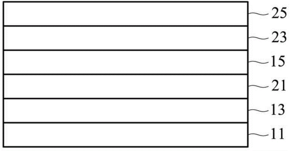
[0046] Take the same three groups of LCDs, after attaching the anti-glare film (fogged PET) on the surface, use optical glue to bond the touch components formed on the cover plate to the anti-glare film on the LCD, and place them on the cover The surface of the plate is coated with an anti-reflection film to form a display touch device (the structure of the display touch device is as follows figure 2 Shown), and measured its optical reflection properties (the measurement standard is MFS-630, the light incident angle is 8 °) as shown in Table 2.

[0047] Table 2

[0048]

[0049] It can be known from ...


PUM

PropertyMeasurementUnit
Thicknessaaaaaaaaaa
Arithmetic mean roughnessaaaaaaaaaa
Thicknessaaaaaaaaaa

Abstract

The invention relates to the field of touch technology, and discloses a display touch device, which includes a display component, a touch component, and an anti-glare film. The anti-glare film is located between the display component and the touch component, wherein the total glare value of the anti-glare film and the display component is between 60 and 80. The above-mentioned anti-glare film may be fogged polyethylene terephthalate, and its thickness is between 100 microns and 300 microns. The invention does not need to greatly change the manufacturing process, and can effectively reduce the reflectivity of the display touch device.

Description

technical field [0001] The invention relates to a display touch device, in particular to a structure for reducing its reflectivity. Background technique [0002] With the advancement of science and technology, various information devices are constantly being introduced, such as mobile phones, tablet computers, ultra-thin notebooks, and satellite navigation. In addition to generally using a keyboard or a mouse for input or manipulation, using touch technology to manipulate an information device is a rather intuitive and popular manipulation method. Among them, the display touch device has a humanized and intuitive input operation interface, so that users of any age can directly select or control information equipment with fingers or stylus, so it is becoming more and more popular in the market. [0003] Existing display touch devices can be roughly divided into touch components and display components. The touch component and the display component can be formed independently...

Claims


Application Information

Patent Timeline
IPC IPC(8): G06F3/041G02F1/1333
Inventor 许毅中徐国书江耀诚谢燕俊张春勇
Owner TPK TOUCH SOLUTIONS (XIAMEN) INC
Why Eureka
Try Eureka