
Encapsulation device and encapsulation method

A packaging device and packaging method technology, which is applied in the manufacture of electrical components, electrical solid devices, semiconductor/solid devices, etc., can solve the problems of prolonging the life of organic light-emitting components, low packaging pass rate, and difficult operation, etc. The effect of lowering the cost of the unit, improving the qualified rate of packaging, and improving the success rate of sintering

Active Publication Date: 2016-10-05
EVERDISPLAY OPTRONICS (SHANGHAI) CO LTD
View PDF5 Cites 0 Cited by
  • Summary
  • Abstract
  • Description
  • Claims
  • Application Information

AI Technical Summary

Problems solved by technology

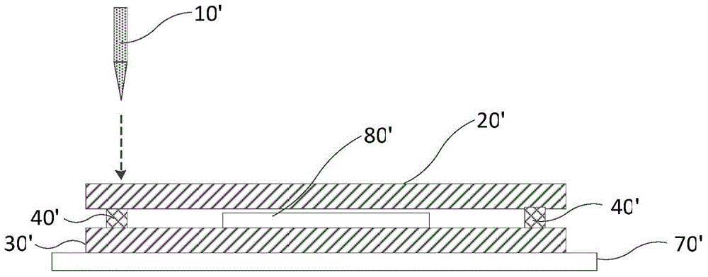
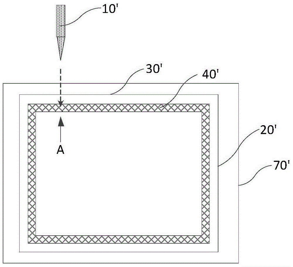
This packaging technology uses a laser or other radiation source to directly heat the glass frit coated between two substrates, melts the glass frit, and then solidifies it to seal the two substrates tightly. At the same time, this localized heating method protects other parts from Damage, so that the components located in the confined space formed by the two substrates and the glass frit are isolated from the outside world, effectively prolonging the life of the organic light-emitting component. This technology has the advantages of local heating, small heating area, fast speed and high efficiency, but Laser sintering of glass frit is difficult and prone to failure, resulting in low packaging pass rate

Method used


Image

  • Encapsulation device and encapsulation method
  • Encapsulation device and encapsulation method
  • Encapsulation device and encapsulation method

Examples


Embodiment Construction

[0043] Example embodiments will now be described more fully with reference to the accompanying drawings. Example embodiments may, however, be embodied in many forms and should not be construed as limited to the embodiments set forth herein; rather, these embodiments are provided so that this disclosure will be thorough and complete, and will fully convey the concept of example embodiments to those skilled in the art. The same reference numerals denote the same or similar structures in the drawings, and thus their repeated descriptions will be omitted.

[0044] Although the encapsulation device of the present invention is described below as an example of encapsulating organic light-emitting elements, it should be understood that the encapsulation device of the present invention can also be used in other same or similar encapsulation or sealing technologies to seal elements or devices in glass or substrate. In the present invention, "upper / upper", "lower / lower", "horizontal", ...


PUM


Abstract

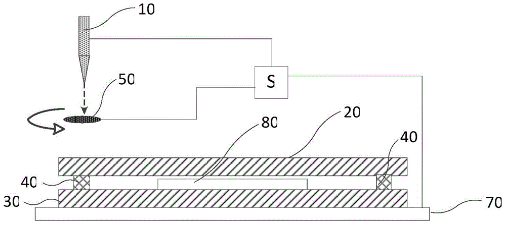
The invention provides an encapsulation device. The encapsulation device is used for encapsulating a component to be encapsulated. The encapsulation device includes a radiation source, a bearing stage which is used for bearing the component to be encapsulated, a shielding piece which is located in the extension direction of a light beam emitted by the radiation source and selectively shields the light beam of the radiation source, and a control module which is used for controlling the shielding piece to make the same allow the light beam of the radiation source to irradiate the component to be encapsulated when the change of the movement speed of the light beam of the radiation source in a time T does not exceed - / +10% and the movement speed of the light beam reaches a steady state, after the energy of the light beam reaches a steady state, wherein the time T is a time required by one-time sintering. The invention also provides a method for carrying out encapsulation by using the above encapsulation device. The shielding piece and the control module are adopted, so that the movement speed and laser energy of the laser or the bearing stage can be in steady states in a sintering process, and the success rate of sintering can be effectively improved.

Description

technical field [0001] The present invention relates to a packaging device and a packaging method, in particular to a device and method for packaging a component to be packaged (such as an organic light-emitting panel) using a radiation source such as a laser or an infrared emitter. Background technique [0002] Organic light-emitting diodes (OLEDs), which have the advantages of high brightness, low driving voltage, fast response, and multi-color performance, have been gradually applied to flat-panel displays. However, the elements of OLEDs are susceptible to the infiltration of moisture and oxygen in the surrounding environment, which will lead to oxidation of electrode materials, reduction of luminous efficiency or color changes, and ultimately shorten the service life of the LEDs. Therefore, in the manufacture of organic light emitting diodes, the encapsulation process is particularly important to completely isolate the organic light emitting diodes from moisture and oxyg...

Claims


Application Information

Patent Timeline
Patent Type & Authority Applications(China)
IPC IPC(8): H01L51/56H01L51/52
Inventor 王演隆王玉清翟宏峰尚卫
Owner EVERDISPLAY OPTRONICS (SHANGHAI) CO LTD
Learn More