Ironless permanent magnet power generation and electric device

A technology for power generation devices and electric devices, applied in the direction of electromechanical devices, electronic reversing motor control, magnetic attraction or thrust holding devices, etc., can solve the problems of complex structure, low power generation efficiency, etc., achieve small size, reduce copper loss , high efficiency effect

Active Publication Date: 2018-05-08
姜志深
View PDF5 Cites 0 Cited by
  • Summary
  • Abstract
  • Description
  • Claims
  • Application Information

AI Technical Summary

Problems solved by technology

[0003] The purpose of the present invention is to provide an iron-free permanent magnet power generation device, which solves the technical problems of complex structure and low power generation efficiency of the existing power generation device

Method used


Image

  • Ironless permanent magnet power generation and electric device
  • Ironless permanent magnet power generation and electric device
  • Ironless permanent magnet power generation and electric device

Examples


Embodiment Construction

[0026] Specific embodiments of the present invention will be described in detail below in conjunction with the accompanying drawings.

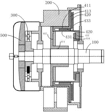
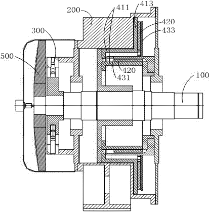
[0027] Such as Figure 1-3 As shown, this embodiment proposes a magnetic levitation coreless permanent magnet power generation device. The power generation device includes a shaft body 100, a casing 200 and a power generation assembly. The casing 200 and the shaft body 100 can rotate relative to each other. The casing 200 generally Installed on the shaft body 100 through bearings. During the relative rotation of the casing 200 and the shaft body 100 , the power generation component generates power.

[0028] This embodiment focuses on explaining the structure of the power generation assembly:

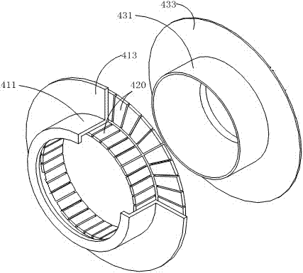
[0029] The casing 200 of this embodiment is an outer stator, and the shaft body 100 is an inner rotor. The power generation assembly includes a rotor assembly and a stator assembly. Wherein, the rotor assembly includes a yoke and a magnet 420 install...


PUM


Abstract

The invention relates to a coreless permanent magnet power generation and electric device. The power generation device comprises a shaft body, a shell and a power generation component. The shell and the shaft body can relatively rotate. The power generation component comprises a rotor component and a stator component. The rotor component comprises a magnet yoke and magnets which are installed on the magnet yoke. The stator component comprises an integrated coil. The magnet yoke comprises at least one cylindrical part which is coaxial with the shaft body and at least one dish-shaped part which is perpendicular to the shaft body. The integrated coil comprises at least one cylindrical part which is coaxial with the shaft body and at least one dish-shaped part which is perpendicular to the shaft body. The cylindrical parts of the magnet yoke and the integrated coil are opposite, and the opposite surfaces of the cylindrical parts of the magnet yoke are provided with magnets. The dish-shaped parts of the magnet yoke and the integrated coil are opposite, and the opposite surfaces of the dish-shaped parts of the magnet yoke are provided with magnets. The coil is integrated so that copper loss can be reduced, damping and iron loss can be eliminated, driving power can be eliminated, thermal loss can be reduced, the size is small, the weight is low, the material can be saved, the speed regulation range is wide and the precision is high.

Description

technical field [0001] The invention relates to the technical field of generators and motors, in particular to an ironless permanent magnet generator motor device. Background technique [0002] The permanent magnet generator is a power generation device that converts mechanical energy into electrical energy. At present, the traditional permanent magnet generator includes an iron core, a permanent magnet rotor, an excitation winding and a slip ring carbon brush, which are primary excitation and secondary excitation respectively. The structure is complex and maintenance is troublesome; due to the limitation of the working magnetic field, the power generation is restricted; there is damping and a starting torque is required, and there is a certain amount of energy consumption while generating power, and the power generation efficiency is low. Contents of the invention [0003] The object of the present invention is to provide an ironless permanent magnet generator, which solv...

Claims


Application Information

Patent Timeline
Patent Type & Authority Patents(China)
IPC IPC(8): H02K21/14H02K21/22H02K9/06H02K1/27H02N15/00H02P6/00
CPCH02K1/2713H02K1/272H02K1/2786H02K9/06H02K21/14H02K21/22H02N15/00H02P6/00
Inventor 姜志深
Owner 姜志深
Why Eureka
Try Eureka