Step and stepless regulation device and regulation method for eccentricity of eccentric shaft

A technology of stepless adjustment and eccentricity, applied in the direction of fluid using vibration, etc., can solve the problems that the eccentricity cannot be adjusted arbitrarily, the mechanism is complicated, and the cost is high, so as to avoid the influence of human factors, simple and fast operation, and good accuracy retention. Effect

Active Publication Date: 2016-10-12
JIANGSU UNIV OF SCI & TECH
View PDF10 Cites 11 Cited by
  • Summary
  • Abstract
  • Description
  • Claims
  • Application Information

AI Technical Summary

Problems solved by technology

However, servo motor drive is required, the mechanism is complicated, the cost is high, and the application is limited
Invention patent "a stepwise adjustment device for eccentricity of eccentric shaft" (ZL201110307143.3), realizes the required eccentricity adjustment by rotating the eccentric disc, and uses the spring to push the dial pin into the pin hole without disassembling the positioning pin and screw, avoiding Influenced by human factors, the operation is simple and fast, and the accuracy of the stepped eccentricity is guaranteed by processing, and the consistency is good, but the disadvantage is that the eccentricity cannot be adjusted arbitrarily. When the required eccentricity is different from the structural preset eccentricity, it cannot meet the requirements.

Method used


Image

  • Step and stepless regulation device and regulation method for eccentricity of eccentric shaft
  • Step and stepless regulation device and regulation method for eccentricity of eccentric shaft
  • Step and stepless regulation device and regulation method for eccentricity of eccentric shaft

Examples


Embodiment Construction

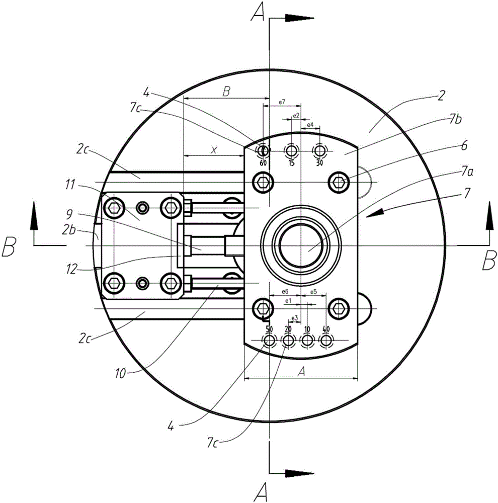
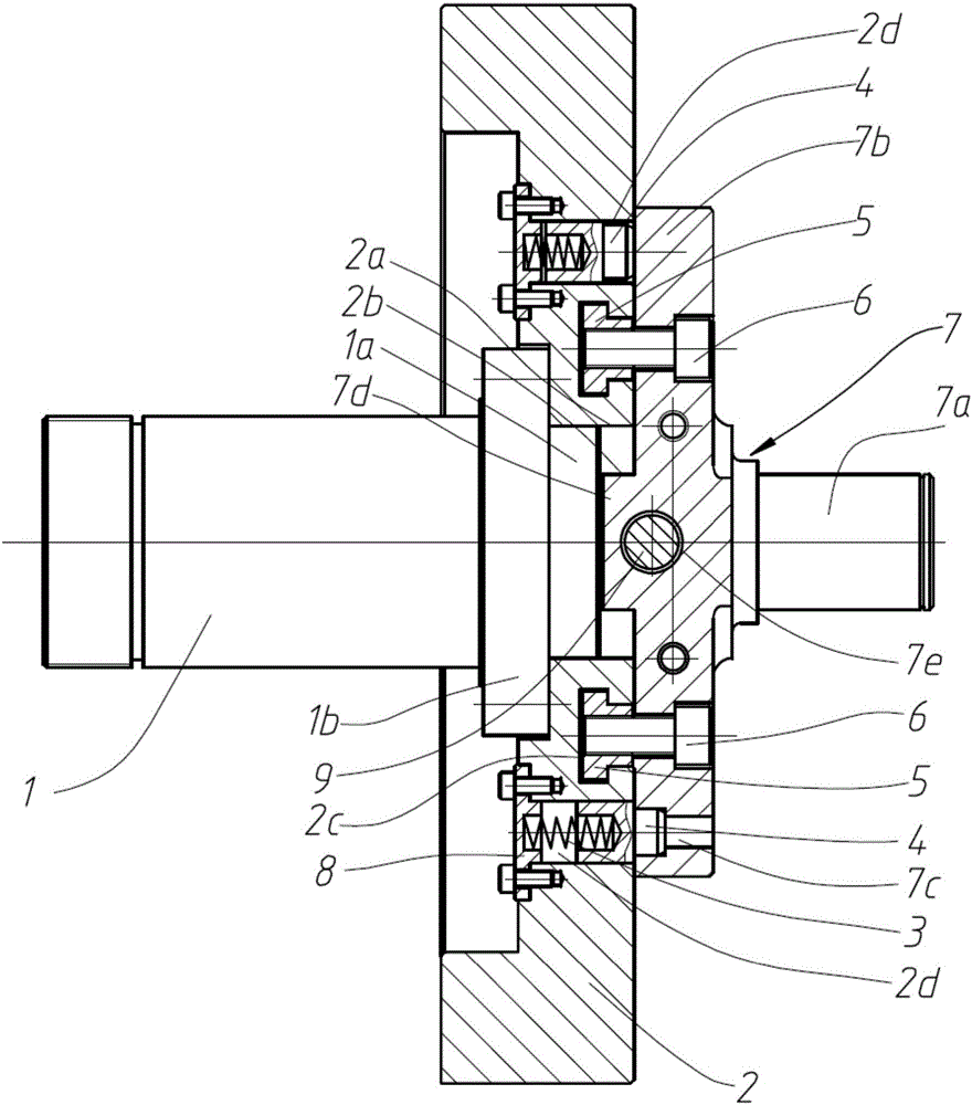
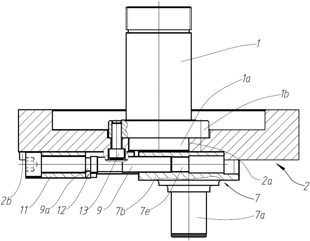
[0022] The technical solution of the present invention will be further specifically described below by taking the eccentric shaft vibration excitation device used in the vehicle shock absorber test bench of the present invention as a specific embodiment, and in conjunction with the accompanying drawings.

[0023] The meanings of "inside and outside" in the present invention refer to that relative to the device itself, the direction pointing to the inside of the device is inward, and vice versa, it is not a specific limitation to the device mechanism of the present invention.

[0024] The meaning of "up and down" described in the present invention refers to: "up" refers to the position at a high place, which is opposite to "down", that is, the upper side; "down" refers to the position at a low place, and " "Up" is relative, that is, the lower layer. Rather than a specific limitation on the mechanism of the device of the present invention.

[0025] The meaning of "left and righ...


PUM


Abstract

The invention discloses a step and stepless regulation device for eccentricity of an eccentric shaft. The step and stepless regulation device comprises a driving shaft, a round disc, a shaft disc, an eccentricity step positioning device and an eccentricity regulation device. Step eccentricity positioning is realized in the mode that one of two spring pins in positioning pin holes symmetrically formed in the round disc up and down is aligned with and inserted into a certain eccentric pin hole in the shat disc, and stepless eccentricity regulation is achieved when the spring pin is inserted into the eccentric pin hole in a non-aligned mode. Guiding is realized through sliding matching of a rectangular groove in the round disc and a rectangular boss on the shaft disc, and regulation is realized through fastening connection or disconnection of two T-shaped grooves in the round disc and the shaft disc through T-shaped nuts and fastening screws. The operation of inserting and pulling out a positioning pin is avoided through step eccentricity positioning with the spring pins, operation is simple and rapid, the regulation accuracy of eccentricity is guaranteed through the position and size precision of each positioning pin hole, the repeatability is good, and the regulation range is wide. The step and stepless regulation device for eccentricity of the eccentric shaft can be used for driving of a slider-crank mechanism and a sine excitation mechanism or other application occasions needing adjustable eccentricity.

Description

technical field [0001] The invention relates to an eccentricity adjustment device, in particular to a mechanical step and stepless adjustment device for the eccentricity of an eccentric shaft. Background technique [0002] In the sinusoidal excitation device, the sinusoidal motion can be realized by hydraulic servo cylinder or frequency conversion motor to drive the eccentric shaft. When the hydraulic servo cylinder is used as the vibration exciter, the ability to steplessly adjust the amplitude within the stroke range of the cylinder can be realized through the displacement sensor. When driven by an eccentric shaft, the adjustment of the eccentricity is relatively troublesome. Usually, a screw nut mechanism is used and a guide rail and a fastening screw are used to move the eccentric shaft relative to the rotation axis to realize stepless adjustment of the eccentricity, but the adjustment accuracy and repeatability are low. The invention patent "Eccentricity Adjustment Met...

Claims


Application Information

Patent Timeline
Patent Type & Authority Applications(China)
IPC IPC(8): B06B1/16
CPCB06B1/162
Inventor 张冰蔚李宏斌周鑫
Owner JIANGSU UNIV OF SCI & TECH
Why Eureka
Try Eureka