Automatic testing device of performance of electromagnet for valve

An automatic testing device and electromagnet technology, which is applied in the direction of measuring devices, measuring electricity, and measuring electrical variables, etc., can solve the need for large-scale testing of electromagnets that are not suitable for valves, increase the labor intensity of testers, and affect the testing speed of electromagnets, etc. problem, to achieve the effect of fast test speed, simple structure, and avoiding the influence of human factors

Inactive Publication Date: 2011-01-05
宁波市鄞州通力液压电器厂
View PDF4 Cites 16 Cited by
  • Summary
  • Abstract
  • Description
  • Claims
  • Application Information

AI Technical Summary

Problems solved by technology

The detection device is not only complex in structure and bulky, but also has many human factors in the test with this detection device, and the test accuracy is low
In addition, the electromagnet is fixed on the electromagnet fixing plate by screws. When the next electromagnet is detected, it is necessary to use tools to remove the electromagnet fixed with screws, and then use tools to install the next electromagnet for detection, thereby affecting the electromagnet. The test speed increases the labor intensity of the testers
The valve electromagnet performance testing device is not suitable for mass testing of valve electromagnets

Method used


Image

  • Automatic testing device of performance of electromagnet for valve
  • Automatic testing device of performance of electromagnet for valve
  • Automatic testing device of performance of electromagnet for valve

Examples


Embodiment Construction

[0016] The present invention will be further described in detail below in conjunction with the accompanying drawings and specific embodiments.

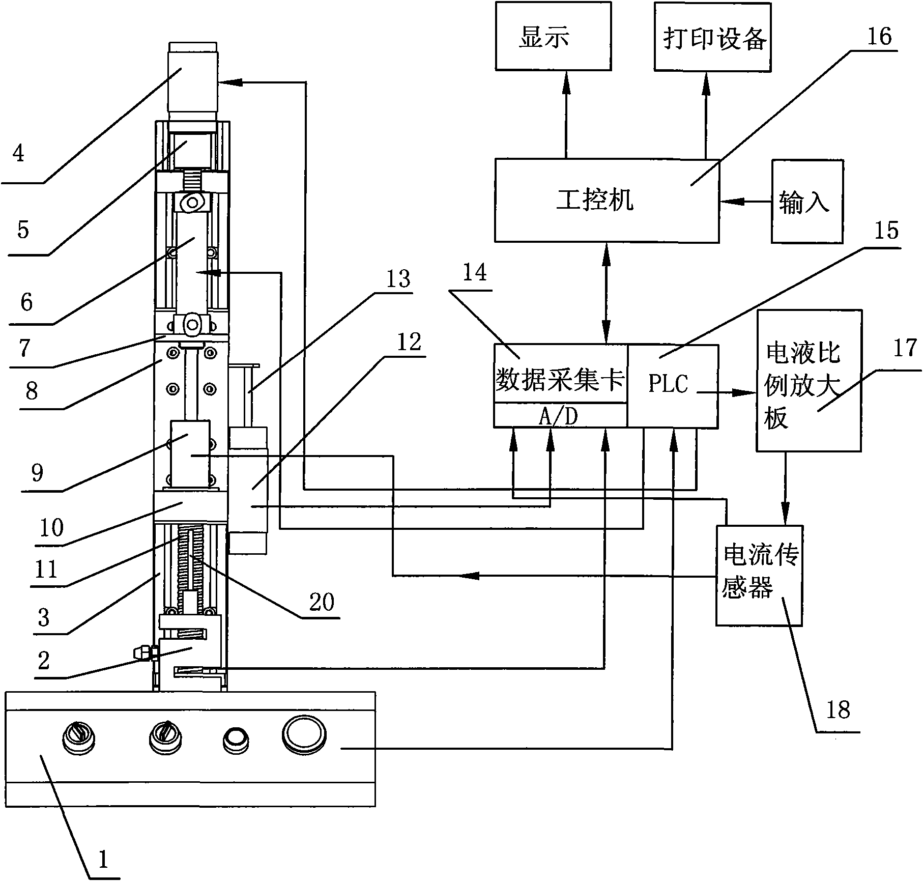
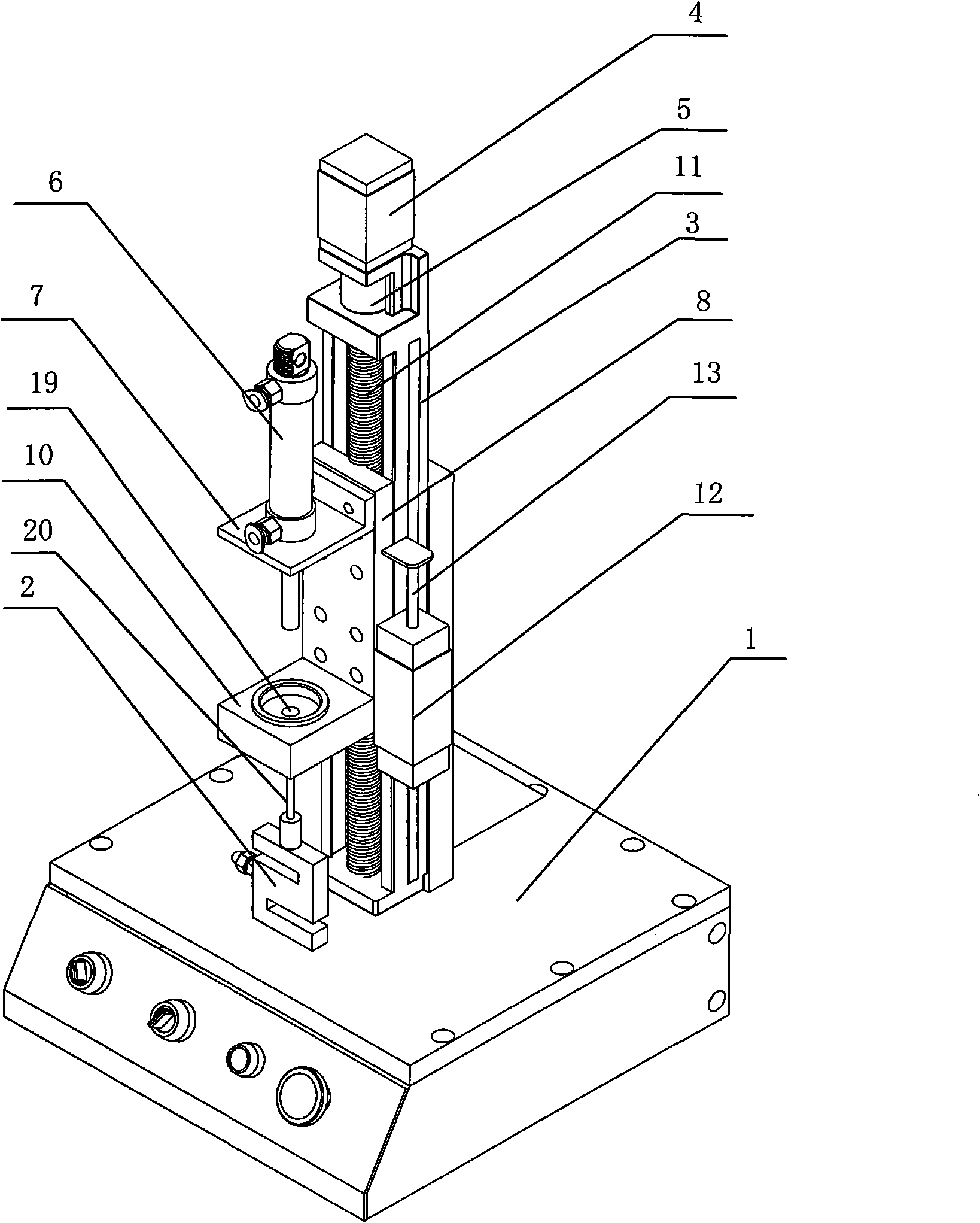
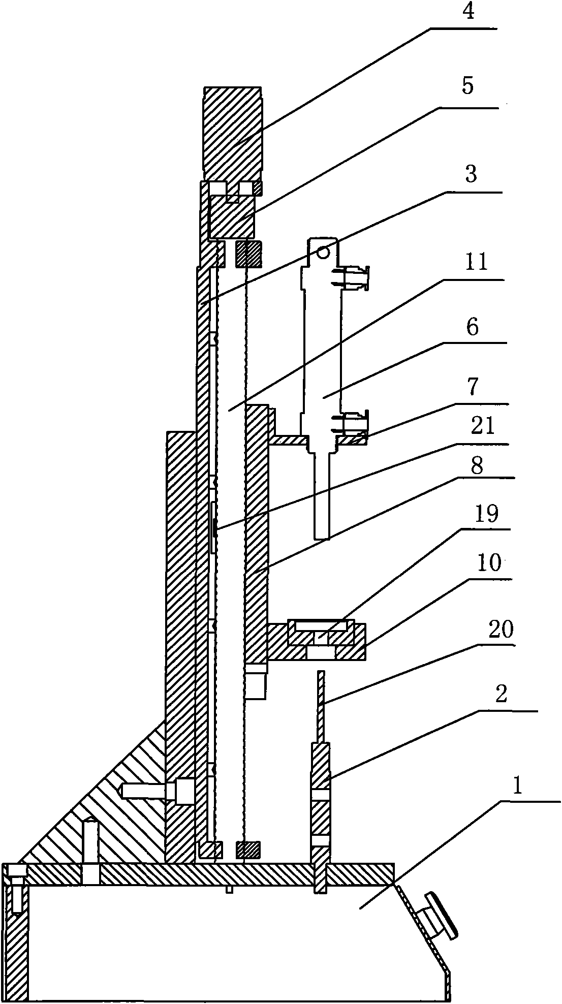
[0017] Such as figure 1 , figure 2 and image 3 shown.

[0018] The valve electromagnet performance automatic testing device of the present invention comprises a workbench 1, a tension pressure sensor 2, a displacement sensor 12, an electro-hydraulic proportional amplifying plate 17, and it also includes a slide block 8 and a linear slide table fixedly connected to the workbench 1. 3. The electromagnet 9 to be tested is placed and fastened on the slider 8, and the slider 8 slides and fits vertically along the linear slide 3, and the tension and pressure sensor 2 is fixed on the workbench 1 below the slider 8, And the contact rod 20 of the pull pressure sensor 2 is located directly below the armature of the electromagnet 9 to be tested, the displacement sensor 12 is fixedly connected on the linear slide table 3, and the free end of...


PUM


Abstract

The invention discloses an automatic testing device of performance of an electromagnet for a valve, which comprises a workbench, a tension and pressure sensor, a displacement sensor, a hydraulic proportional amplifying plate, a slide block and a linear slipway which is fixedly connected with the workbench. The electromagnet to be tested is placed and fastened on the slide block; the slide block is in slide fit in the vertical direction of the linear slipway; the tension and pressure sensor is fixed on the workbench under the slide block; a touch rod of the tension and pressure sensor is positioned at the right lower part of an armature of the electromagnet to be tested; the displacement sensor is fixedly connected to the linear slipway; and the free end of a slide rod of the displacement sensor is fixed on the slide block. The automatic testing device also comprises a programmable logic controller, a data collecting card, a current sensor and an industrial control computer, wherein the programmable logic controller is electrically connected with the hydraulic proportional amplifying plate and an operating button on the workbench respectively; and the data collecting card is electrically connected with the displacement sensor, the tension and pressure sensor, the current sensor and the industrial control computer respectively.

Description

technical field [0001] The invention relates to the field of electromagnet performance testing, in particular to an automatic testing device for valve electromagnet performance. Background technique [0002] At present, in the automotive field, hydraulic solenoid valves are used in the actuators of electro-hydraulic control systems of automotive continuously variable transmissions. The hydraulic solenoid valves in the actuators of the electro-hydraulic control systems are generally electromagnetic proportional pressure reducing valves and electromagnetic proportional relief valves. , The accuracy of the electromagnetic proportional pressure reducing valve and the electromagnetic proportional overflow valve directly affects the performance of the continuously variable transmission of the car. The characteristics of the proportional electromagnet, one of the important parts of the electromagnetic proportional pressure reducing valve and electromagnetic proportional relief valv...

Claims


Application Information

Patent Timeline
Patent Type & Authority Applications(China)
IPC IPC(8): G01R31/00
Inventor 陈晓齐
Owner 宁波市鄞州通力液压电器厂
Why Eureka
Try Eureka