
Swinging type clamping device

A clamping device and swing-type technology, which is applied in the field of mechanical processing, can solve problems such as poor synchronization, and achieve good clamping effect, good stability, and good clamping effect

Inactive Publication Date: 2016-10-12
桐乡守敬应用技术研究院有限公司
View PDF5 Cites 10 Cited by
  • Summary
  • Abstract
  • Description
  • Claims
  • Application Information

AI Technical Summary

Problems solved by technology

However, at present, multiple pressure plates are driven by individual cylinders, and the synchronization is poor.

Method used


Image

  • Swinging type clamping device
  • Swinging type clamping device

Examples


Embodiment Construction

[0013] The present invention will be further described in detail below in conjunction with the accompanying drawings and examples. The following examples are explanations of the present invention and the present invention is not limited to the following examples.

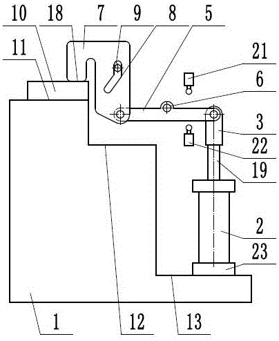
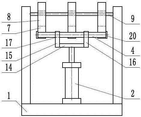
[0014] Such as figure 1 and figure 2 As shown, a swing clamping device includes a frame 1, a drive cylinder 2, a support assembly 3, a drive shaft 4, a lever 5, a support shaft 6, a pressure plate 7, a long hole 8, a guide pin shaft 9, a strip shaped workpiece 10, the frame 1 is provided with a first step 11, a second step 12 and a third step 13, the elongated workpiece 10 is placed on the first step 11, and the driving cylinder 2 includes a cylinder 23 and the piston rod 19, the cylinder body 23 is installed vertically on the third step 13, the upper end of the piston rod 19 is connected to the support assembly 3, and the support assembly 3 includes the support plate 14, the left lug 15 and the right support The...


PUM


Abstract

The invention provides a swinging type clamping device, and belongs to the technical field of machining. The swinging type clamping device comprises a supporting assembly, two or more levers and pressing plates, and a long strip-shaped workpiece is placed on a first step; a cylinder body of a driving cylinder is vertically mounted on a third step; the upper end of a piston rod is connected with the supporting assembly; a left supporting lug and a right supporting lug of the supporting assembly are symmetrically fixed on the left and right sides of a supporting plate; hinge holes are formed in the left supporting lug and the right supporting lug; a supporting shaft is fixed to a rack; the middle ends of the levers are hinged to the supporting shaft; a driving shaft is fixedly connected with one ends of the levers; the driving shaft penetrates through the hinge holes of the left supporting lug and the right supporting lug; the other ends of the levers are hinged to the lower ends of the pressing plates; pressing heads are arranged on the pressing plates; long holes are further formed in the pressing plates; and guide hinge pins are fixed to the rack, and penetrate through the long holes. According to the swinging type clamping device, the driving cylinder drives the plurality of pressing plates, the long strip-shaped workpiece is clamped, and the clamping effect is good.

Description

technical field [0001] The invention relates to the technical field of machining, in particular to a swing clamping device. Background technique [0002] Machining refers to the process of changing the shape or performance of a workpiece through a mechanical device. According to the difference in processing method, it can be divided into cutting processing and pressure processing. In the production process, the process of changing the shape, size, position and nature of the production object to make it a finished or semi-finished product is called a process. It is an essential part of the production process. The process can be divided into casting, forging, stamping, welding, machining, assembly and other processes. The mechanical manufacturing process generally refers to the sum of the machining process of parts and the assembly process of machines. Other processes are called auxiliary processes. Processes, such as transportation, storage, power supply, equipment mainten...

Claims


Application Information

Patent Timeline
Patent Type & Authority Applications(China)
IPC IPC(8): B23Q3/08B25B5/06B25B5/14
CPCB23Q3/069B23Q3/064B23Q3/066B25B5/064B25B5/14
Inventor 邱洪波
Owner 桐乡守敬应用技术研究院有限公司
Learn More