
A mechanical arm structure

A technology for manipulators, manipulators, and manipulators. It is applied in the direction of manipulators, manufacturing tools, and joints. It can solve the problems of inability to accurately locate the coordinates of the target, uncertainty between the lens and the target, and difficulty in arranging the camera components in parallel with the end of the manipulator on the same plane, etc. problem, to achieve the effect of simple structure, reliable connection and improved work performance

Inactive Publication Date: 2018-07-06
WUHU RUNZHONG ROBOT TECH CO LTD
View PDF5 Cites 0 Cited by
  • Summary
  • Abstract
  • Description
  • Claims
  • Application Information

AI Technical Summary

Problems solved by technology

[0002] The camera and the end actuator of the manipulator in the prior art mainly fix the main board of the camera module at the end of the manipulator. It is difficult to ensure that the camera assembly and the end actuator of the manipulator are arranged in parallel and on the same plane during installation, resulting in , the lens cannot be kept perpendicular to the target image, because of the uncertainty of the angle between the lens and the target object when taking photos, resulting in the inability to accurately locate the coordinates of the target object

Method used


Image

  • A mechanical arm structure
  • A mechanical arm structure
  • A mechanical arm structure

Examples


Embodiment Construction

[0019] Below with reference to the accompanying drawings, through the description of the embodiments, the specific embodiments of the present invention, such as the shape, structure, mutual position and connection relationship between the various parts, the role and working principle of the various parts, etc., will be further described. Detailed instructions:

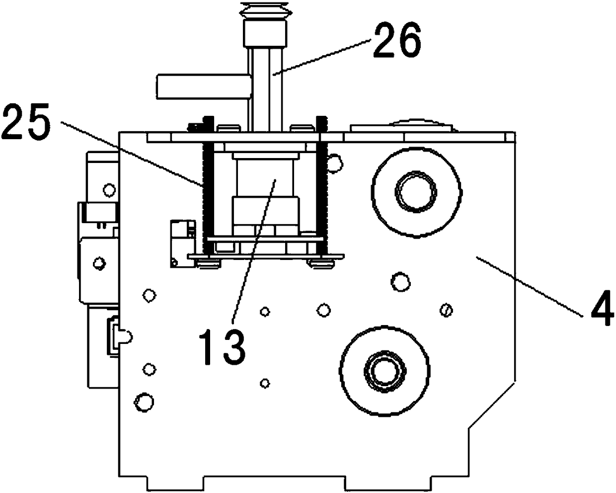
[0020] as attached figure 1 — attached image 3 As shown, the present invention is a mechanical arm structure of a manipulator. The end of the manipulator arm is provided with a manipulator end actuator 1, and a fixed bracket 2 is installed on the manipulator end actuator 1. The fixed bracket includes a left bracket 3 and a right bracket. 4. The cover plate 5 at the end of the manipulator, the left bracket 3 and the right bracket 4 are connected by a plurality of connecting screws 6, and the end actuator 1 of the manipulator is set as a structure that can be fixedly clamped between the left bracket 3 and the right bra...


PUM


Abstract

The invention provides a manipulator mechanical-arm structure applied to the field of manipulator equipment. The manipulator mechanical-arm structure is characterized in that a fixed bracket (2) is mounted on a manipulator tail-end actuator (1); a left bracket (3) and a right bracket (4) of the fixing bracket are connected through a plurality of connecting screws (6); the manipulator tail-end actuator (1) is set as a structure that can be fixedly clamped between the left bracket (3) and the right bracket (4); a manipulator tail-end cover plate (5) is connected with the upper surface of the left bracket (3) and the upper surface of the right bracket (4); and a camera component (8) is mounted on an extension plate (7). The manipulator mechanical-arm structure provided by the invention is simple in structure and can ensure that the positions of the camera component and the manipulator tail-end actuator are fixed relatively and the camera component and the manipulator tail-end actuator are parallel to each other; and the lower end surface of the camera component and the manipulator tail-end actuator are located on the same horizontal plane so as to improve the precision of a manipulator.

Description

technical field [0001] The invention belongs to the field of manipulator equipment, and more specifically relates to a manipulator arm structure. Background technique [0002] The camera and the end actuator of the manipulator in the prior art mainly fix the main board of the camera module at the end of the manipulator. It is difficult to ensure that the camera assembly and the end actuator of the manipulator are arranged in parallel and on the same plane during installation, resulting in , the lens cannot be kept perpendicular to the target image, because of the uncertainty of the angle between the lens and the target object when taking photos, resulting in the inability to accurately locate the coordinates of the target object. Contents of the invention [0003] The technical problem to be solved by the present invention is: to provide a simple structure, which can ensure that the relative position between the camera assembly and the end actuator of the manipulator is fi...

Claims


Application Information

Patent Timeline
Patent Type & Authority Patents(China)
IPC IPC(8): B25J17/00
CPCB25J17/00
Inventor 薛鹏陈新
Owner WUHU RUNZHONG ROBOT TECH CO LTD
Learn More