Flexible unit and flexible wrist

A flexible and limiting technology, applied in the field of mechanical wrists, can solve the problems of limited flexible center position, damage, tearing of the rubber layer, etc., and achieve the effect of improving stability and avoiding damage.

Active Publication Date: 2016-10-12
SHEN ZHEN GLI TECH LTD
View PDF14 Cites 0 Cited by
  • Summary
  • Abstract
  • Description
  • Claims
  • Application Information

AI Technical Summary

Problems solved by technology

However, the flexible wrist for robots designed by helical springs has the following disadvantages: due to the fixed structure of the helical springs, the flexible center position of the flexible wrist device formed by the helical springs is limited, and the horizontal and angular error compensation capabilities are also very limited. Therefore, it is difficult to Large-scale application in industry
However, the composite mechanism of metal and rubber still has the following disadvantages: the structure lacks a self-limiting device; the structure has a certain degree of flexibility, but under a large load, due to large deformation, it may cause tearing and destruction of the rubber layer

Method used


Image

  • Flexible unit and flexible wrist
  • Flexible unit and flexible wrist
  • Flexible unit and flexible wrist

Examples


Embodiment 1

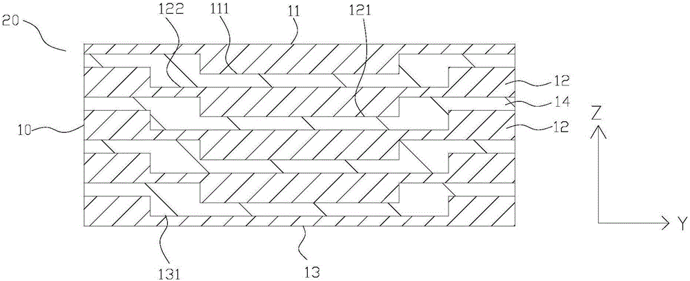
[0034] Such as figure 1 The shown flexible unit 20 includes a strip-shaped flexible body 10. The flexible body 10 has a head stopper 11 and a plurality of middle stoppers 12 stacked at intervals along the length direction of the flexible body 10 and all have rigidity. and a tail limiter 13, the head limiter 11 and the tail limiter 13 are separately arranged at both ends of the flexible body 10; the side of the middle limiter 12 close to the head limiter 11 is recessed to form a first blind hole 122 , the first limiting portion 121 formed on the other side of the middle limiting member 12 near the tail limiting member 13; the first limiting portion 121 of one of the two adjacent middle limiting members 12 The bit portion 121 extends into the first blind hole 122 of the other middle stopper 12, and is used to abut against the wall of the first blind hole 122; the side part of the head stopper 11 close to the middle stopper 12 The protrusion forms a second stopper 111, and the s...

Embodiment 2

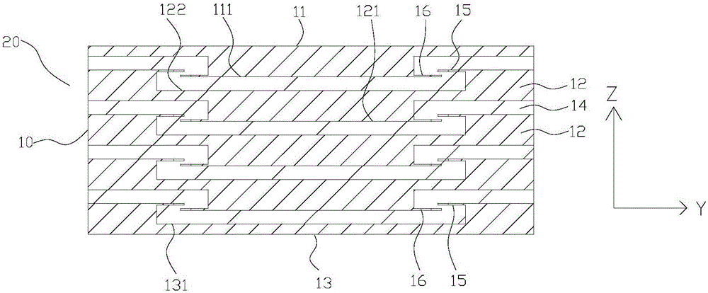
[0039] Such as figure 2 As shown, the difference between the second embodiment and the first embodiment is that the top ends of the walls of the first blind hole 122 and the second blind hole 131 in this embodiment are provided with an annular flange 15, and each first limiting portion 121 The ring mouth of the annular flange 15 extends into the first blind hole 122 and the second blind hole 131 respectively, and the outer walls of the ends of the first limiting parts 121 extend into the first blind hole 122 and the second blind hole 131 Both are provided with an annular clamping portion 16; the second limiting portion 111 extends into the first blind hole 122 from the ring mouth of the annular flange 15, and the second limiting portion 111 extends into the end outer wall of the first blind hole 122. There is an annular clamping part 16; since the annular clamping part 16 of the first limiting part 121 can abut and fit with the side wall of the annular flange 15 facing the bl...

Embodiment 3

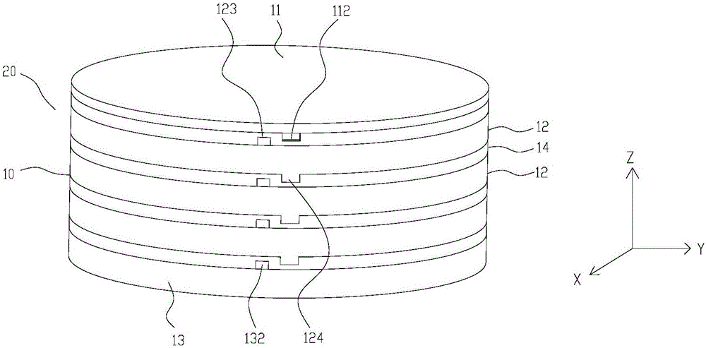
[0041] Such as image 3 As shown, the difference between the third embodiment and the second embodiment is that the two sides of the middle limiting member 12 in this embodiment are respectively provided with a first convex portion 123 and a second convex portion 124, which are close to the middle limiting member 12 The side portions of the head limiter 11 and the tail limiter 13 are respectively provided with a third protrusion 112 and a fourth protrusion 132, therefore, when the flexible body 10 rotates along its axial direction, two adjacent middle limiters The first convex portion 123 of one of the middle limiting pieces 12 in the pieces 12 can abut against the second convex portion 124 of the other middle limiting piece 12, and the middle limiting piece adjacent to the head limiting piece 11 The first protrusion 123 of 12 can be abutted with the third protrusion 112 of the head limiter 11, and the second protrusion 124 of the middle limiter 12 adjacent to the tail limiter...


PUM


Abstract

The invention discloses a flexible unit. The flexible unit comprises a strip-shaped flexible body, and the flexible body is internally provided with a head limiting piece, a plurality of middle limiting pieces and a tail limiting piece which are overlapped at intervals in the length direction of the flexible body; one side of each middle limiting piece close to the head limiting piece is inwards concaved to form a first blind hole, and the other side of each middle limiting piece close to the tail limiting piece is protruded to form a first limiting portion; the first limiting portion of one of every two adjacent middle limiting pieces stretches into the first blind hole of the other middle limiting piece; the side portion of the head limiting piece close to the middle limiting pieces is protruded to form a second limiting portion, and the second limiting portion stretches into the first blind hole of the middle limiting piece adjacent to the head limiting piece; the side portion of the tail limiting piece close to the middle limiting pieces is inwards concaved to form a second blind hole, the first limiting portion of the middle limiting piece adjacent to the tail limiting piece stretches into the second blind hole, and the flexible unit can integrate flexibility and a self-limiting function. The invention further discloses a flexible wrist adopting the flexible unit.

Description

technical field [0001] The invention relates to a mechanical wrist, in particular to a flexible unit and a flexible wrist. Background technique [0002] In the robot automatic assembly operation, due to the repeatable positioning accuracy error of the robot and the material delivery system, the tolerance of the fixture and the processing tolerance of the parts, etc., there will be assembly errors (including horizontal direction and angular direction) between the parts to be assembled, Generally, the assembly precision between the parts to be assembled is relatively high, especially in 3C (computer, communication and consumer electronics equipment) and other fields that require precision assembly, which makes the robot unable to complete the assembly task. Therefore, robotic automated precision assembly systems must include devices to eliminate assembly errors. This assembly error can be eliminated by improving the motion and machining accuracy of robots, material delivery s...

Claims


Application Information

Patent Timeline
Patent Type & Authority Applications(China)
IPC IPC(8): B25J17/02
CPCB25J17/0208
Inventor 刘阳
Owner SHEN ZHEN GLI TECH LTD
Why Eureka
Try Eureka