
Design method for hypersonic speed inner and outer flow integrated full wave rider flight vehicle

A hypersonic, design method technology, applied in aircraft parts, ground installations, transportation and packaging, etc., can solve the difficulty of controlling the size of the lip shock and bottom shock, reduce the design freedom of the precursor shock, and limit the design type. line shape etc.

Active Publication Date: 2016-10-12
NAT UNIV OF DEFENSE TECH
View PDF5 Cites 29 Cited by
  • Summary
  • Abstract
  • Description
  • Claims
  • Application Information

AI Technical Summary

Problems solved by technology

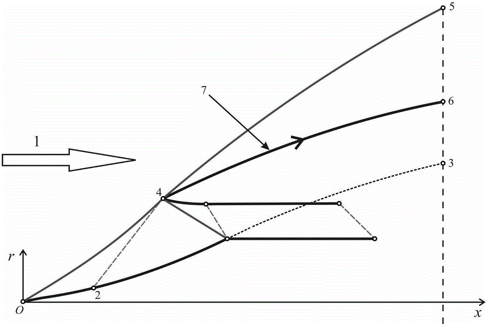
The defects of the axisymmetric reference flow field model based on the pointed rotor based on the integration of internal and external flow are as follows: figure 1 , where 1 represents the supersonic incoming flow condition, 2 represents the intersection of the left-handed Mach line passing through the lip point 4 and the wall surface of the pointed rotary body O-3; 3 represents the pointed rotary body generatrix O-3 at the bottom of the rotary body The end point of the cross-section; 4 indicates the lip point; 5 indicates the leading edge shock wave O-4-5 of the pointed gyrator around the generatrix O-3 at the end point of the bottom cross-section; 6 indicates passing through the lip point 4 The streamline at the end point of the bottom cross-section; 7 indicates the streamline passing through the lip point 4
Design the pointed rotor (O-3), under the action of supersonic incoming flow condition 1, the leading edge shock wave (O-5) is generated by the pointed rotor, and the lip point 4 converts the leading edge shock wave (O-5) Divided into two sections of shock, namely the front body shock (O-4) and the back body shock (4-5); therefore the front body shock (O-4) and the back body shock (4-5) At position 4, not only the first-order derivative is continuous, but also the second-order derivative is continuous, that is, the curvature is continuous, which reduces the respective design degrees of freedom of the front body shock (O-4) and the rear body shock (4-5), that is, the front The shock angle of the shock wave (O-4) at the lip point 4 and the shock angle of the rear body shock wave (4-5) at the lip point 4 cannot be individually designed; at the same time, the model is also difficult to Control the size of the lip shock and bottom shock, which is not conducive to the design of the size of the aircraft front body and rear body
In addition, since the profile line of the outer wall of the lip cover (ie 4-6) is a streamline generated by applying streamline tracing in the reference flow field around the pointed body of revolution, this also limits the design of the profile line (ie 4 -6) Shape

Method used


Image

  • Design method for hypersonic speed inner and outer flow integrated full wave rider flight vehicle
  • Design method for hypersonic speed inner and outer flow integrated full wave rider flight vehicle
  • Design method for hypersonic speed inner and outer flow integrated full wave rider flight vehicle

Examples


Embodiment Construction

[0084] The design method of a hypersonic internal and external flow integrated full waverider aircraft provided by the present invention will be described in detail below in conjunction with the accompanying drawings.

[0085] Step S1, designing an axisymmetric reference flow field model based on an arbitrary axisymmetric reference shock wave integrating internal and external flows.

[0086] The specific steps for designing the benchmark flow field model are described in S1.1-S1.7 below.

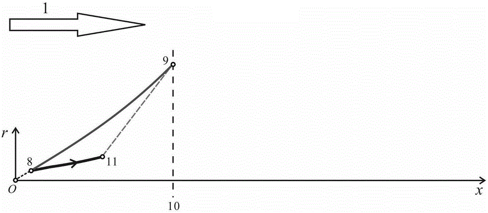
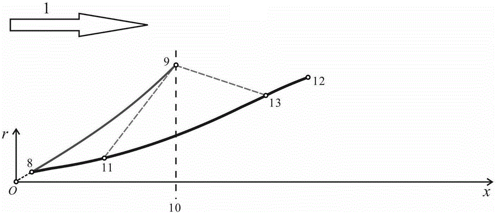
[0087] S1.1, if figure 2 As shown, given the shape of the precursor shock wave 8-9, 8 is the starting point of the precursor shock wave, and 9 is the end point of the precursor shock wave, which is also the lip point of the inlet port, and the cross section passing through point 9 is taken as The inlet lip cross-section of the reference flow field 10 .

[0088] The supersonic incoming flow condition 1 and the precursor shock wave 8-9 are used as input conditions. The supersonic incoming f...


PUM


Abstract

The invention relates to a design method for a hypersonic speed inner and outer flow integrated full wave rider flight vehicle. The method comprises the following steps: firstly, designing an inner and outer flow integrated axial symmetrical standard flow field model based on a random axial symmetrical standard shock wave; giving a projection curve of a flight vehicle front-body front edge line, an air inlet lip shaped line and a wing front edge line at the bottom cross section, starting from the front-body front edge line and the air inlet lip shaped line, tracking the streamline in a front body-air inlet standard flow field area and generating a wave rider front body-air inlet; starting from the air inlet lip shaped line and the wing front edge line, tracking the streamline in a rear body standard flow field area, generating an engine body web wave rider surface and a wing wave rider surface and forming a rear body wave rider surface by the engine body web wave rider surface and the wing wave rider surface; taking the free flow surface as an upper surface and forming a wave rider engine body-air inlet integrated structure by the upper surface, the wave rider front body-air inlet and rear body wave rider surface. Different front and rear body shock waves can be designed according to the requirement, so that the degree of freedom of the design for the front and rear body shock waves can be increased.

Description

technical field [0001] The invention relates to the technical field of aerodynamic shape design of an air-breathing hypersonic vehicle, in particular to a design method for a full waverider vehicle with integrated internal and external flow at hypersonic speed based on an arbitrary axisymmetric reference shock wave. Background technique [0002] An air-breathing hypersonic vehicle refers to an aircraft with a flight Mach number greater than 5, powered by an air-breathing engine or a combined engine, and capable of long-distance flight in the atmosphere and across the atmosphere. Its application forms include hypersonic cruise missiles, hypersonic Manned / unmanned aircraft and aerospace aircraft and other aircraft. [0003] A large number of studies since the 1960s have fully demonstrated that the integrated design of the propulsion system and the airframe is the key to the realization of hypersonic flight, and it is one of the key technologies to be solved urgently in hyperso...

Claims


Application Information

Patent Timeline
Patent Type & Authority Applications(China)
IPC IPC(8): B64F5/00
CPCB64F5/00
Inventor 丁峰柳军沈赤兵刘珍黄伟王源杰罗仕超陈韶华符翔
Owner NAT UNIV OF DEFENSE TECH
Learn More