Film forming device and partition wall structure of same

A film-forming device and a technology for partition walls, which are applied in ion implantation plating, gaseous chemical plating, coating, etc., can solve problems such as difficulty in improving thin films

Inactive Publication Date: 2016-10-12
KOBE STEEL LTD
View PDF5 Cites 2 Cited by
  • Summary
  • Abstract
  • Description
  • Claims
  • Application Information

AI Technical Summary

Problems solved by technology

Therefore, it is difficult to improve the thickness distribution of the film

Method used


Image

  • Film forming device and partition wall structure of same
  • Film forming device and partition wall structure of same
  • Film forming device and partition wall structure of same

Examples


Embodiment Construction

[0066] Hereinafter, embodiments of the partition wall structure and the film forming apparatus including the partition wall structure of the present invention will be described in further detail with reference to the drawings.

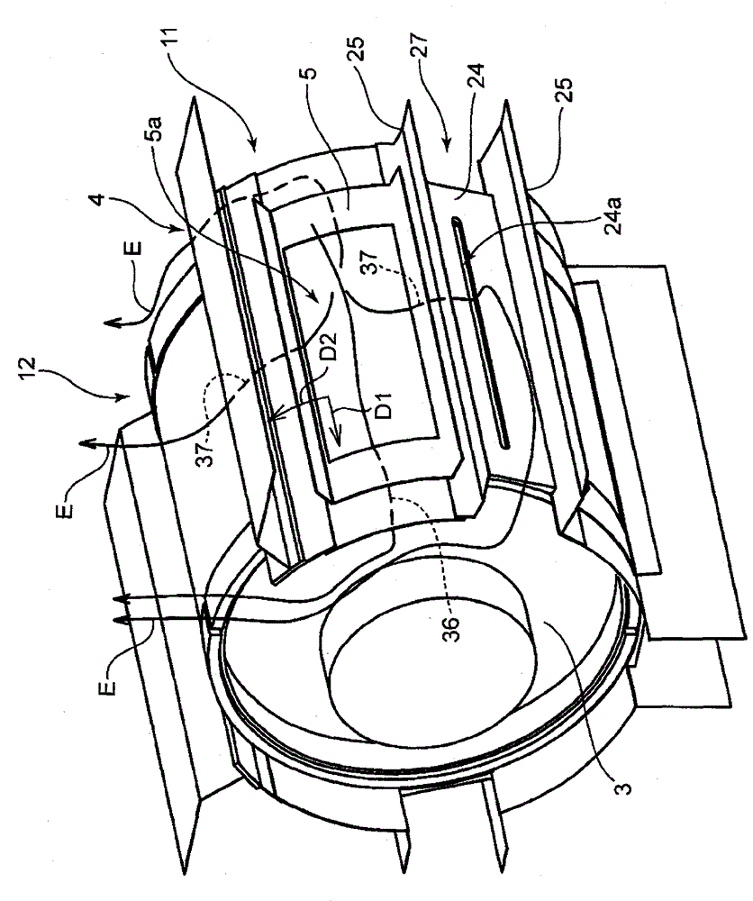
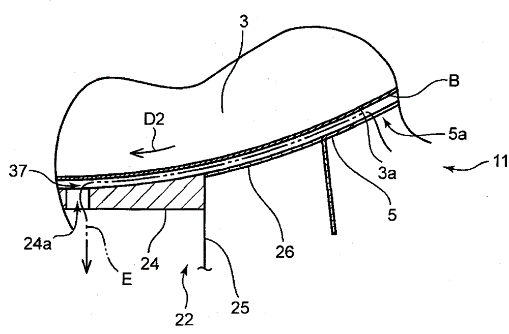
[0067] Figure 1 ~ Figure 2 The shown film forming device 1 is formed on at least one partition wall structure 4 (in figure 1 4 in the middle) A device for continuously forming a thin film on the surface of the strip-shaped substrate B using the gas G in the film forming area 11 . As the film forming apparatus 1, any apparatus that continuously forms a thin film on the surface of the substrate B using the gas G may be used, and a film forming apparatus that performs sputtering, vacuum deposition, plasma CVD, or the like is used. In the following embodiments, the film formation apparatus 1 that performs sputtering will be described as an example.

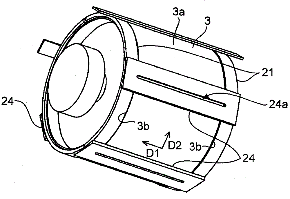
[0068] This film forming apparatus 1 includes a chamber 2 , a film forming roll 3 rotatably mounted insi...


PUM


Abstract

Provided is a partition wall structure for a film forming apparatus and a film forming apparatus, wherein the partition wall structure of the present invention forms at least one film formation region in the chamber of the film forming apparatus. The partition wall structure includes a circumferential regulating portion and a pair of partition walls. The circumferential restricting portion is connected to the partition wall so that the relative position of the circumferential regulating portion and the partition wall is fixed. The inner side surface of the partition wall faces the outer peripheral surface of the film formation roller with a gap therebetween when the partition wall is attached to the chamber. The circumferential direction regulating portion forms a film formation area facing the outer peripheral surface of the film formation roller. The film forming apparatus of the present invention comprises a pair of partition walls fixed to the chamber and disposed on both sides in the widthwise direction of the film formation roller at positions spaced from the film roll by a partition wall. An outer surface facing the radially outer side of the film formation roll and an inner surface facing radially inward of the film formation roll, the mask being mounted on the outer side surface of the partition wall, the inner side surface of the partition wall being located closer to the outer peripheral surface of the film roll and is positioned radially inwardly of the film formation roller.

Description

technical field [0001] The present invention relates to a film forming apparatus for forming a film on the surface of a substrate, and a partition wall structure for forming a film forming region inside a chamber in the film forming apparatus. Background technique [0002] Conventionally, among the film-forming apparatuses that continuously form a film on the surface of a strip-shaped substrate wound on a film-forming roll, there is a film-forming apparatus in which a plurality of film-forming zones are formed inside a chamber, and each In the film formation area, film formation is performed under individual film formation conditions (for example, pressure, composition of material gas, etc.). In such a film-forming apparatus, the pressure inside each film-forming region needs to be maintained at a pressure determined for each film-forming region while maintaining a pressure higher than the pressure outside the film-forming region. [0003] Therefore, conventionally, as desc...

Claims


Application Information

Patent Timeline
Patent Type & Authority Applications(China)
IPC IPC(8): C23C14/56C23C14/24C23C14/04
CPCC23C14/042C23C14/24C23C14/562C23C14/564C23C16/042C23C16/4409C23C16/4412C23C16/455C23C16/545
Inventor 濑川利规大庭尚树井亦辉
Owner KOBE STEEL LTD
Why Eureka
Try Eureka