
Excavator

A technology of excavator and walking body, which is applied in the field of excavator

Active Publication Date: 2016-10-12
SUMITOMO HEAVY IND LTD
View PDF8 Cites 6 Cited by
  • Summary
  • Abstract
  • Description
  • Claims
  • Application Information

AI Technical Summary

Problems solved by technology

Therefore, the upper limit of the digging force is limited according to the allowable maximum pressure of the hydraulic pressure on the boom cylinder rod side.

Method used

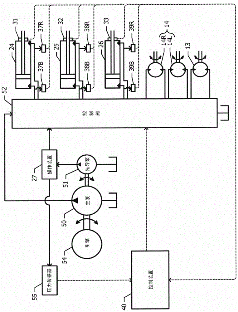
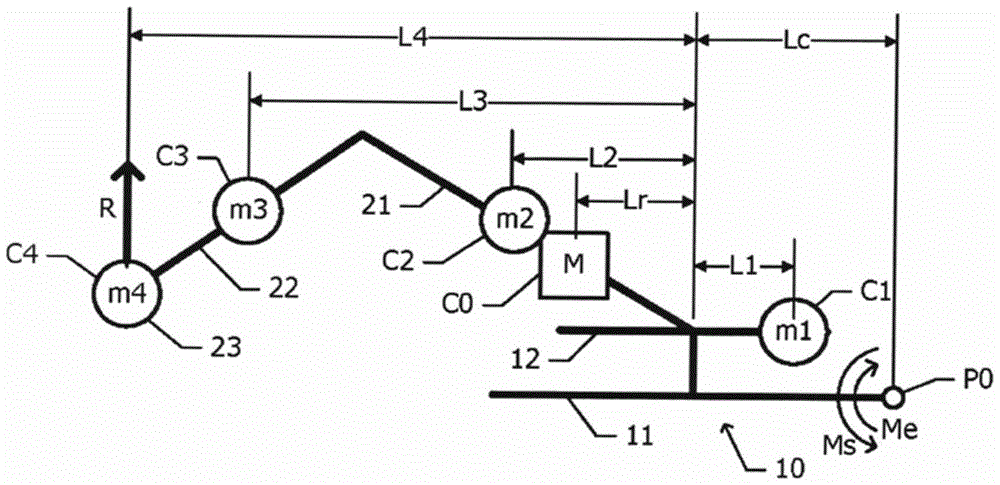

Image

  • Excavator
  • Excavator
  • Excavator

Examples


Embodiment Construction

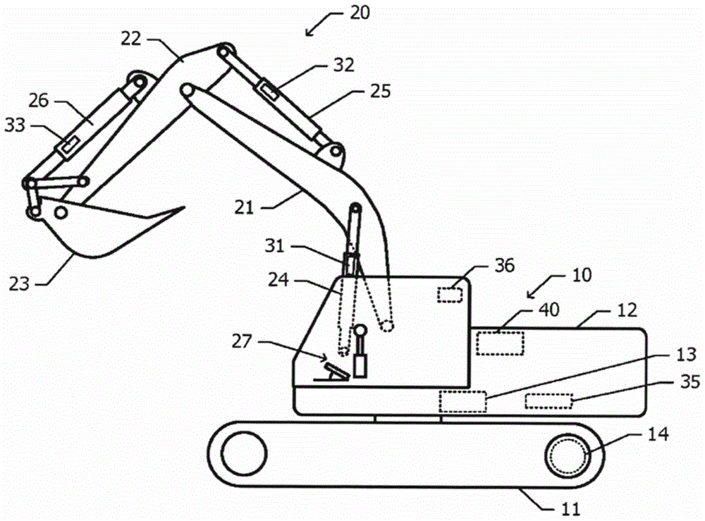
[0031] figure 1 A schematic side view of the shovel of the embodiment is shown in . The main body 10 of the shovel includes a lower traveling body 11 and an upper revolving body 12 . The upper revolving body 12 is mounted on the lower traveling body 11 so as to be able to turn.

[0032] The turning drive device 13 mounted on the upper turning body 12 turns the upper turning body 12 relative to the lower traveling body 11 . The traveling drive device 14 mounted on the undercarriage 11 rotates the left and right crawlers of the undercarriage 11 to make the undercarriage 11 run and turn relative to the ground contact surface. If the left and right crawlers are rotated in opposite directions at the same speed, the undercarriage 11 does not need to move, but turns on the spot. This type of turn is often referred to as "steering in place". Hydraulic motors can be used for the turning drive device 13 and the traveling drive device 14 .

[0033] Attachments 20 are mounted on the ...


PUM


Abstract

The invention provides an excavator which inhibits floation and has high excavation force. An upper revolving body can be revolvably supported on the lower travel body. A revolve driving apparatus enable the upper revolving body to revolve relative to the lower travel body. The upper revolving body is provided with accessory which revolves along with the upper revolving body. If work conditions are satisfied, a control apparatus drives the revolve driving apparatus to work, so that the upper revolving body is revolved to the direction causing floation of the lower travel body due to excavation reactive force applied on an acting point of the accessory.

Description

technical field [0001] This application claims priority based on Japanese Patent Application No. 2015-064250 filed on March 26, 2015. The entire contents of this Japanese application are incorporated herein by reference. [0002] The invention relates to an excavator. Background technique [0003] Patent Document 1 below discloses a shovel capable of maintaining good excavation work efficiency by utilizing the dead weight of the shovel to the maximum. In the shovel disclosed in Patent Document 1, the allowable maximum pressure of the hydraulic pressure on the side of the boom cylinder rod is required according to the magnitude of the excavation reaction force when the shovel floats due to the excavation reaction force. During excavation, control the boom cylinder so that the hydraulic pressure on the boom cylinder rod side does not exceed the allowable maximum pressure. [0004] Patent Document 1: Japanese Patent Laid-Open No. 2014-122510 [0005] In the shovel disclosed...

Claims


Application Information

Patent Timeline
Patent Type & Authority Applications(China)
IPC IPC(8): E02F9/24
CPCE02F9/24
Inventor 古庄健太郎牧野史纪
Owner SUMITOMO HEAVY IND LTD
Learn More