Slab supporting construction method and construction device by reversely suspending template

A construction method and construction device technology, which is applied in the field preparation of formwork/formwork/work frame, building components, construction, etc., can solve the problems of long construction period, high cost of mechanical shifts, and difficulty in binding steel bars, etc. Achieve the effect of improving the overall construction progress, reducing the erection cost, and reducing the erection period

Inactive Publication Date: 2016-10-12
GUANGZHOU CONSTR ENG +1
View PDF13 Cites 12 Cited by
  • Summary
  • Abstract
  • Description
  • Claims
  • Application Information

AI Technical Summary

Problems solved by technology

[0003] Among them, the full house floor support needs to be erected on the ground or the next floor. Such erection has a long construction period, a large investment in turnover materials, and a high investment cost. It can only be carried out after the support is removed, which restricts the construction of the lower floor; especially for super high formwork, there is a safety hazard due to poor overall stability of the full house support
[0004] Among them, the use of reinforced truss formwork or profiled steel plate floor slabs first requires the use of crane equipment to assist hoisting, which takes up the use of hoisting equipment and the vertical transportation time of the crane, and the cost of mechanical shifts is high; secondly, the reinforced truss formwork or profiled steel plate floor bearings The steel content of the slab is large, and the cost is high; moreover, it is difficult to bind the steel bars of the steel truss formwork; while the profiled steel plate floor slab has high ribs, and the thickness of the floor structure layer is large, which reduces the net height of the building, and the lower surface of the floor slab is Wavy shape, uneven and unattractive slab bottom, inconsistent two-way rigidity of the floor slab, cumbersome binding of steel bars, and short steel bars need to be manually welded on-site for the lower stressed steel bars, resulting in slow efficiency

Method used


Image

  • Slab supporting construction method and construction device by reversely suspending template
  • Slab supporting construction method and construction device by reversely suspending template
  • Slab supporting construction method and construction device by reversely suspending template

Examples


Embodiment Construction

[0032] Embodiments of the present invention will be described in detail below in conjunction with the accompanying drawings.

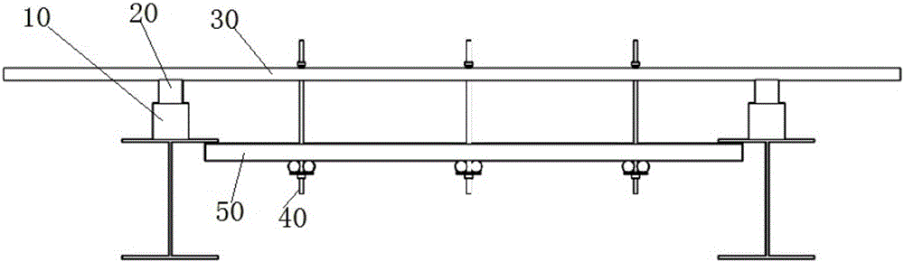
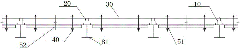
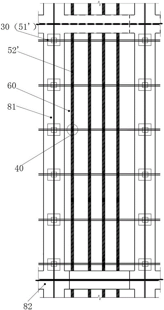
[0033] Such as figure 1 — Figure 5 A schematic diagram of the floor support construction device and construction method of the reverse-hanging formwork of the present invention is shown. in figure 1 and figure 2 In the middle, the wooden frame sub keel of the lower layer is parallel to the upper keel, and the steel pipe main keel of the lower layer is perpendicular to the upper keel; Figure 3-Figure 5 In the middle, the wooden frame sub-keel of the lower layer is perpendicular to the upper-layer keel, and the steel-pipe main keel of the lower layer is parallel to the upper-layer keel; other structures are the same, and will be explained together below.

[0034] The template to be constructed is a steel-concrete composite structure, which includes a steel structure 80 and a concrete structure to be poured. To pour concrete on the steel structure...


PUM


Abstract

The invention relates to a slab supporting construction method by reversely suspending a template. The slab comprises a steel structure and a concrete structure to be poured, wherein the steel structure comprises steel beams. The slab supporting construction method by reversely suspending a template comprises the following steps: (1) prefabricating concrete blocks, and mounting the concrete blocks on the steel beams according to the interval which is calculated by stress after the designed strength is achieved, wherein the height of the concrete blocks equals to that of a to-be-poured slab; (2) arranging a wood cushion block on each concrete block which is already arranged; (3) putting an upper keel on the wood cushion block which is already arranged to enable the upper keels to cross a plurality of steel beams; (4) mounting split suspenders in a suspending manner downward from the upper keels, and mounting corresponding lower keels for the lower ends of the split suspenders; (5) laying a template on the lower keels; and (6) pouring concrete. The invention further relates to the construction device in the construction method.

Description

technical field [0001] The invention belongs to the field of building construction engineering, and relates to a concrete pouring support construction method and a construction device, in particular to a floor support construction method and a construction device for reverse-hanging formwork. Background technique [0002] At present, super high-rise buildings and railway platforms mostly adopt the floor structure of steel-concrete composite structure. In the prior art, there are mainly two types of support systems for floor pouring of cast-in-place concrete floors with high storey heights: 1. use full house floor supports, and 2. use reinforced truss formwork or profiled steel plate floor support. [0003] Among them, the full house floor support needs to be erected on the ground or the next floor. Such erection has a long construction period, a large investment in turnover materials, and a high investment cost. It can only be carried out after the support is removed, which...

Claims


Application Information

Patent Timeline
Patent Type & Authority Applications(China)
IPC IPC(8): E04G11/48
CPCE04G11/48
Inventor 赖泽荣黄俊峰
Owner GUANGZHOU CONSTR ENG
Why Eureka
Try Eureka