Disc cutter type multiple drill bit suitable for hard-to-drill stratum
A composite drill bit and disc cutter technology, applied in construction and other directions, can solve the problems of interlocking failure of cutting teeth, falling off of cutting teeth, and inability to re-enter the well for use.
- Summary
- Abstract
- Description
- Claims
- Application Information
AI Technical Summary
Problems solved by technology
Method used
Image
Examples
Embodiment 1
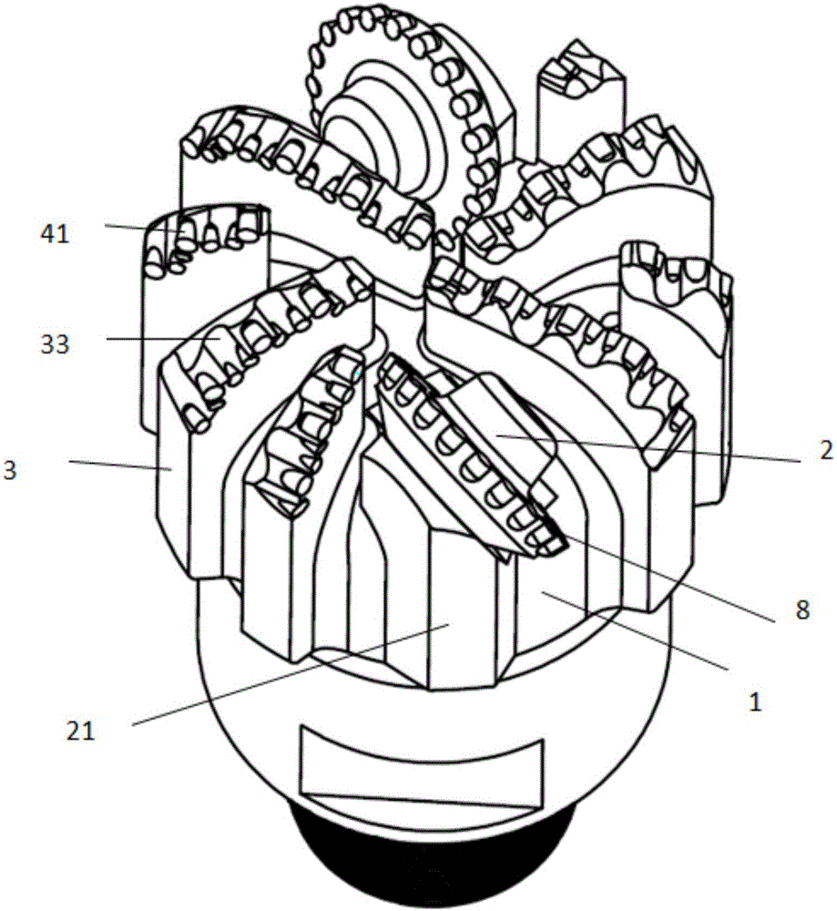
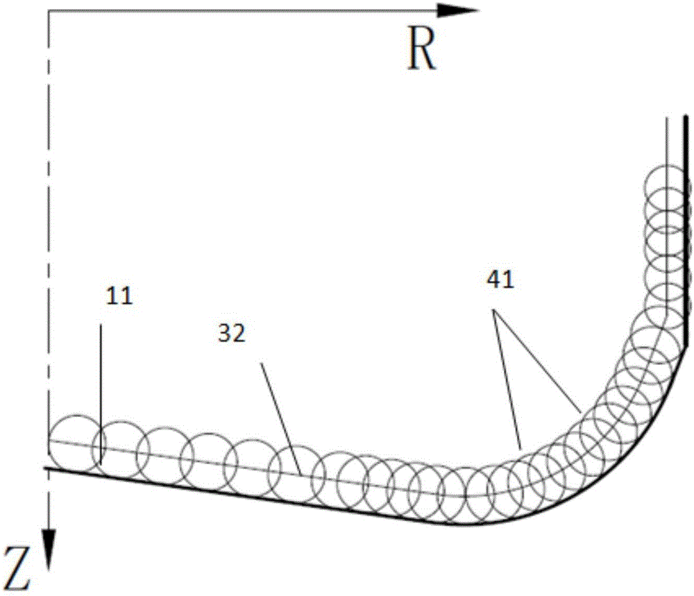
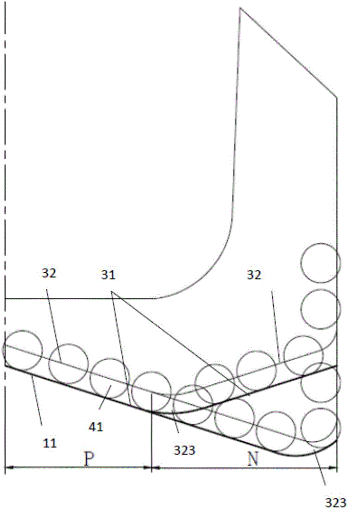
[0111] Such as figure 1 , 11, 12, and 13 show a disc cutter drill with asynchronous cutting principles, including a drill body 1, a plurality of blades 3 extending to the drill body 1, a disc cutter 2 that is rotatably connected to the drill body 1, and arranged on the drill body. The water eye or nozzle 61 on the body 1, the wheel palm 21 is arranged on the drill body 1, the disc cutter 2 is installed on the wheel palm 21, and forms a rotational connection with the wheel palm 21, and the disc cutter 2 is arranged outside the disc cutter body by the disc cutter body. The blades 3 are provided with several first groups of cutting teeth 41, and the tooth surface 33 of the blades 3 is provided with dimples for fixing the first group of cutting teeth 41. Between the blades Water eyes or nozzles 61 are arranged in the flow passage, and the body outline 32 of at least one blade 3 (may include a front blade body outline and a rear blade body outline) and at least one other blade 3 ...
Embodiment 2
[0118] Such as Figure 14 As shown, this embodiment is basically the same as Embodiment 1, the difference is that the disc cutter 2 includes at least three protrusions 321 to form a wave-shaped or star-shaped disc cutter, such as Figure 15 shown. Figure 16 for Figure 14 (In order to clearly see the contour line of the blade body and the contour line of the outer edge of the disc cutter, only the tooth arrangement of the two blades is given).
Embodiment 3
[0120] Such as Figure 17 , 18 As shown, the present embodiment is basically the same as the first embodiment, the difference is that the disc cutter 2 is directly fixed on the blade 3, and is arranged on the front side of the blade 3, while in the first or second embodiment, the disc cutter is set The wheel palm 21 is independently arranged on the drill body. In this embodiment, the disc cutter is directly arranged on the blade body, which saves the valuable space of the drill bit, and the disc cutter 2 does not replace the tooth arrangement on the cutter wing 3, that is, the total diamond tooth arrangement volume of the drill bit is not reduced. As well known to researchers in the field, the disc cutter 2 can also be provided with the blade 3 on the rear side of the blade 3, and the disc cutter can be arranged on both the front and rear sides of the blade 3 body.
PUM
| Property | Measurement | Unit |
|---|---|---|
| Height | aaaaa | aaaaa |
Abstract
Description
Claims
Application Information
 - R&D
- Intellectual Property
- Life Sciences
- Materials
- Tech Scout
- Unparalleled Data Quality
- Higher Quality Content
- 60% Fewer Hallucinations
Browse by: Latest US Patents, China's latest patents, Technical Efficacy Thesaurus, Application Domain, Technology Topic, Popular Technical Reports.
© 2025 PatSnap. All rights reserved.Legal|Privacy policy|Modern Slavery Act Transparency Statement|Sitemap|About US| Contact US: help@patsnap.com


