Thick wing group of large turbine blade

A wind turbine blade and airfoil family technology, applied in the field of horizontal axis wind turbine airfoil design, can solve the problems of deviation from optimal torsion angle, unfavorable blade structural strength and rigidity, and poor performance, so as to reduce pressure gradient and save materials Amount and cost, effect of increased strength and structural rigidity

Active Publication Date: 2016-10-12
申振华
View PDF7 Cites 1 Cited by
  • Summary
  • Abstract
  • Description
  • Claims
  • Application Information

AI Technical Summary

Problems solved by technology

Although these thick airfoils in the inner and root transition sections contribute less to the overall work of the wind turbine, for long blades, the cumulative effect of a slight increase in the performance of each section of the airfoil cannot be ignored. Cumulative economic benefits generated within may far exceed their manufacturing cost
In addition, as the blades are getting longer and longer, in order to adapt to different incoming flow directions, the greater the twist angle of the airfoil between the blade tip and the root is required, which is detrimental to blade manufacturing and structural strength and rigidity; according to the blade design theory, The root torsion angle is often very large, but due to manufacturing constraints, it generally does not exceed 20° at present, which greatly deviates from the optimal torsion angle required by the theoretical inflow angle
For the thick airfoil at the root, the actual working angle of attack of the airfoil is often very large, and the design angle of attack of the thick airfoil itself (especially the sharp trailing edge) is very small, which is easy to cause flow separation, so the airfoil often works at a stall state, its performance is naturally poor
Or because people have not paid enough attention to the airfoil at the root of the blade and other reasons, the research results of thick airfoils with a relative thickness of more than 45% (including 45%) are rarely published in the world before, so the development of wind turbine technology is in urgent need. Research results of thick airfoils on the inner side, especially in the transition section

Method used


Image

  • Thick wing group of large turbine blade
  • Thick wing group of large turbine blade
  • Thick wing group of large turbine blade

Examples


specific Embodiment approach

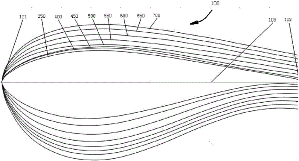
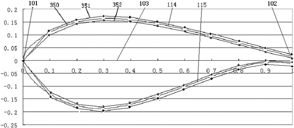
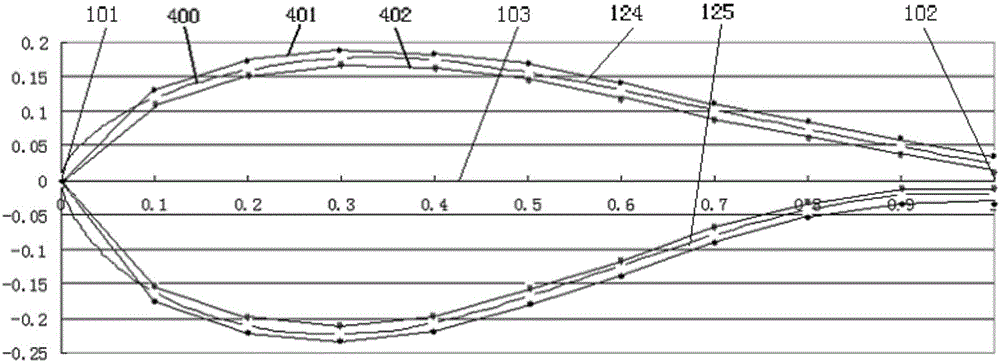
[0083] In order to achieve the above goals, the present invention is aimed at each airfoil in the above-mentioned airfoil family, which is characterized in that the suction surface of the airfoil is lower, the pressure surface is more convex, the thickness of the trailing edge is larger, the pressure surface is S-shaped after loading, and the leading edge Larger radius. According to the above-mentioned basic idea, the present invention uses the Profil i Pro based on Xfoil (the software based on the vortex surface element method of viscous-inviscid iteration developed by the U.S. MIT, the airfoil calculation in the state before the subsonic speed stall has sufficient precision) The software constructs a new airfoil, including relative camber size and position change, relative thickness size and position change, leading edge radius and trailing edge thickness change, etc., and performs performance calculation under smooth conditions under the condition of Re=3000000 , and finall...


PUM


Abstract

The invention belongs to the field of design of horizontal axis wind power wings, and in particular, relates to a thick wing group of a large turbine blade. The thick wing group comprises eight wings with relative thicknesses of 0.35, 0.40, 0.45, 0.50, 0.55, 0.60, 0.65 and 0.70; the eight wings all have thicker blunt tail edges, and are suitable for the inner side and the root part of an above-MW-grade large turbine blade working under high reynolds number; the thick wing group is higher in rise coefficient, lift-to-drag ratio and stall attack angle compared with a traditional contrast wing, so that higher rise and torque are provided to the blade, the start air speed of a turbine is lower, the power coefficient is higher, and the output power is higher; the designed larger attack angle facilitates reduction of the twisting angle of the blade, and facilitates the structural design of the blade and the rigidity, strength and manufacturing of a blade girder, so that the turbine blade of the thick wing group is lighter; and meanwhile, the blunt tail edge design of the wing improves the blade manufacturability, and effectively reduces the production cost.

Description

technical field [0001] The invention belongs to the field of horizontal axis wind turbine airfoil design, in particular to the inside and root airfoils of large wind turbine blades above MW level working under high Reynolds number. Background technique [0002] The blade is the core component of the wind turbine to capture wind energy for energy conversion, and the airfoil is the most important component of the blade, especially the outer and tip airfoils of the blade, which have a decisive impact on the aerodynamic performance of the wind turbine, so people usually Only focus on the study of the outer and tip thin airfoils. With the maturity of wind turbine design technology, in recent years, people have also begun to pay attention to the research on the airfoil of the inner and root transition sections, and the shape of the transition section of the blade root is usually determined by the thickness of the blade (that is, near the root) and the airfoil. Interpolate between...

Claims


Application Information

Patent Timeline
IPC IPC(8): F03D1/06F03D80/00
CPCF03D1/0625F03D1/0675Y02E10/72Y02P70/50
Inventor 申振华
Owner 申振华
Why Eureka
Try Eureka