Turbine blade dimple

a turbine blade and dimple technology, applied in the field of turbine blade dimple, to achieve the effect of increasing the frequency of the natural vibration of the turbine blade, reducing the weight of the blade, and maintaining performan

Inactive Publication Date: 2005-12-20
PRATT & WHITNEY CANADA CORP
View PDF8 Cites 49 Cited by
  • Summary
  • Abstract
  • Description
  • Claims
  • Application Information

AI Technical Summary

Benefits of technology

[0008]The invention provides an apparatus and a method of increasing the frequency of the natural vibration of a turbine blade, while reducing blade weight, maintaining performance and adding no cost, by forming a recess on the pressure side of the blade close to but not intersecting with the blade tip.

Problems solved by technology

A disadvantage of the prior art method is that the geometry of the tip of the blade is an important factor in determining the aerodynamic properties of the blade, the structural integrity of the blade and the maintenance of appropriate clearances with a surrounding shroud.

Method used


Image

  • Turbine blade dimple
  • Turbine blade dimple
  • Turbine blade dimple

Examples


Embodiment Construction

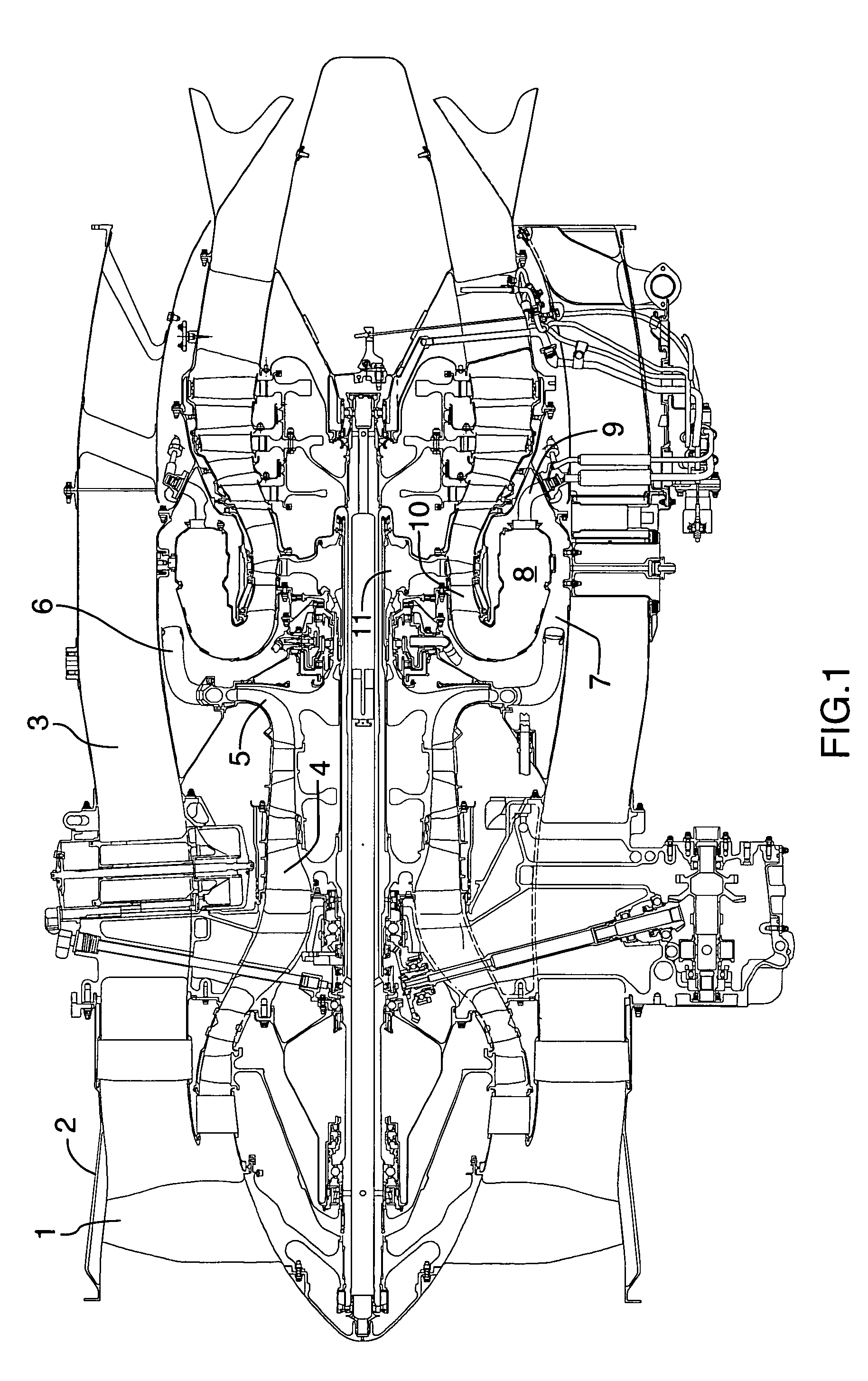
[0022]FIG. 1 shows an axial cross-section through a typical turbofan gas turbine engine. It will be understood however that the invention is applicable to any type of engine with a combustor and turbine section such as a turboshaft, a turboprop, auxiliary power unit, gas turbine engine or industrial gas turbine engine. Air intake into the engine passes over fan blades 1 in a fan case 2 and is then split into an outer annular flow through the bypass duct 3 and an inner flow through the low-pressure axial compressor 4 and high-pressure centrifugal compressor 5. Compressed air exits the compressor 5 through a diffuser 6 and is contained within a plenum 7 that surrounds the combustor 8. Fuel is supplied to the combustor 8 through fuel tubes 9 which is mixed with air from the plenum 7 when sprayed through nozzles into the combustor 8 as a fuel air mixture that is ignited. A portion of the compressed air within the plenum 7 is admitted into the combustor 8 through orifices in the side wal...


PUM


Abstract

A blade for mounting in an annular array about a rotary hub, the blade having: a blade root; an airfoil profile with a concave pressure side surface; a chord line extending between a leading edge and a trailing edge; and a blade tip, where the blade has a recess in the pressure side surface with an outer periphery disposed radially inwardly from the blade tip, and inwardly along the chord line from the leading edge and from the trailing edge.

Description

TECHNICAL FIELD[0001]The invention relates to a method of increasing the frequency of the natural vibration of a turbine blade, while reducing blade weight, maintaining performance and adding minimal or no cost, by forming a recess on the pressure side of the blade close to but not intersecting with the blade tip.BACKGROUND OF THE ART[0002]The invention relates to formation of a recess adjacent to a blade tip of blades mounted in turbines, compressor rotors, or fan blades, in a gas turbine engine.[0003]In order to tune the blades to achieve dynamic benefits such as vibration stress reduction and weight reduction, the prior art has included recesses in the air foil surfaces of blades. The high rotary speeds and dynamic interaction with gas flow creates simultaneous need for weight reduction, maintenance of aerodynamic performance, measurement of blade creep growth but primarily for balancing dynamic vibratory effects.[0004]For example, U.S. Pat. No. 4,265,023 provides a creep growth ...

Claims


Application Information

Patent Timeline
Patent Type & Authority Patents(United States)
IPC IPC(8): F01D5/14F01D5/16
CPCF01D5/141F01D5/145F01D5/20F05D2270/17F05D2240/30Y10S416/50
Inventor ROY, FRAN.CEDILLA.OISBLAIS, DANY
Owner PRATT & WHITNEY CANADA CORP
Why Eureka
Try Eureka