A road energy harvesting device
What is Al technical title?
Al technical title is built by PatSnap Al team. It summarizes the technical point description of the patent document.
A technology of collecting device and road energy, applied in the direction of machines/engines, mechanical equipment, mechanisms that generate mechanical power, etc., can solve the problems of many hydraulic oil pipeline interfaces, loose pipeline interfaces, easy leakage of hydraulic oil, etc., which is not easy to achieve. Leakage, avoid shock and vibration, and ensure the effect of long-term stable work
Active Publication Date: 2018-11-06
北京龙波之光新能源科技有限公司
View PDF8 Cites 2 Cited by
Summary
Abstract
Description
Claims
Application Information
AI Technical Summary
This helps you quickly interpret patents by identifying the three key elements:
Problems solved by technology
Method used
Benefits of technology
Problems solved by technology
In practical application, the energy harvesting device with this structure requires multiple hydraulic cylinders to be arranged on the road at the same time to form a speed bump, resulting in too many hydraulic oil pipeline connections. The looseness of the pipeline interface makes the hydraulic oil easy to leak
Method used
Image
Click on the blue label to locate the original text in one second.
Reading with bidirectional positioning of images and text.
Examples
Embodiment Construction
[0035] The technical solution of the present invention will be described in detail below in conjunction with the accompanying drawings.
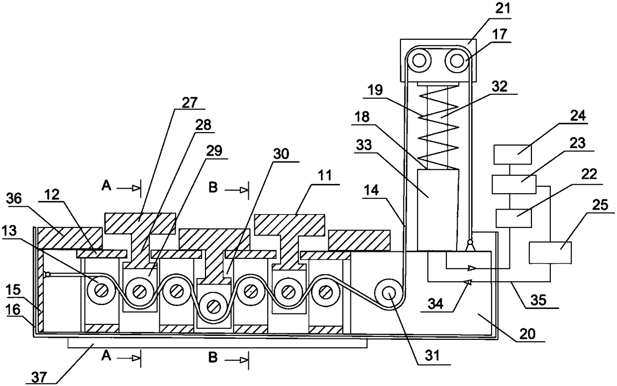
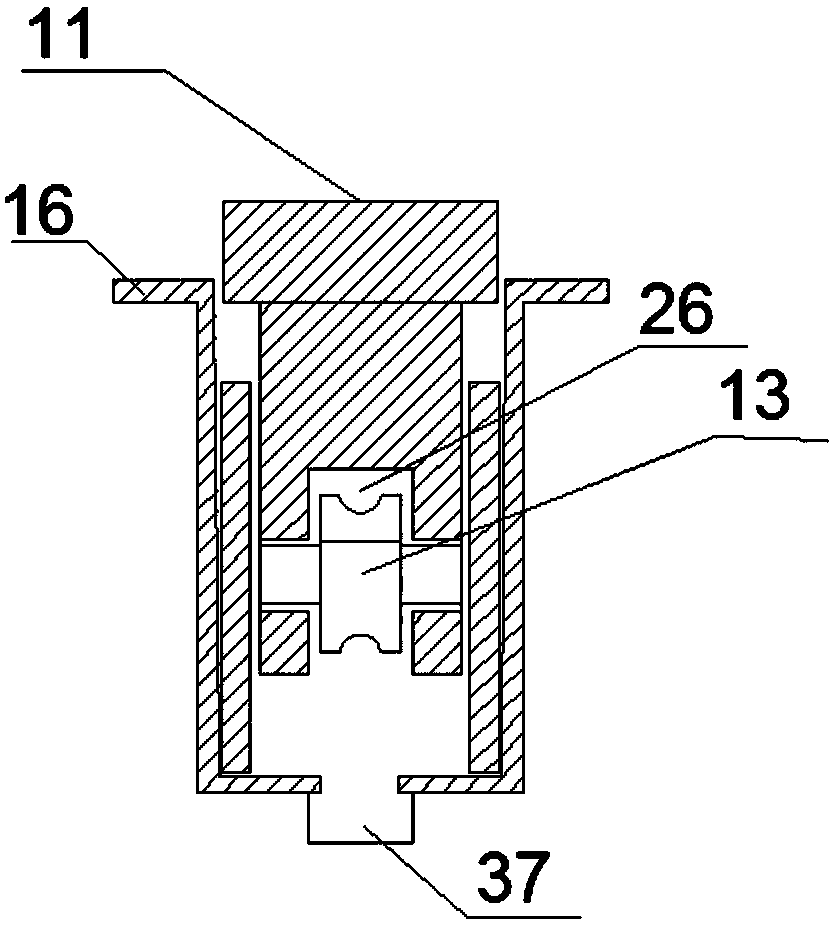
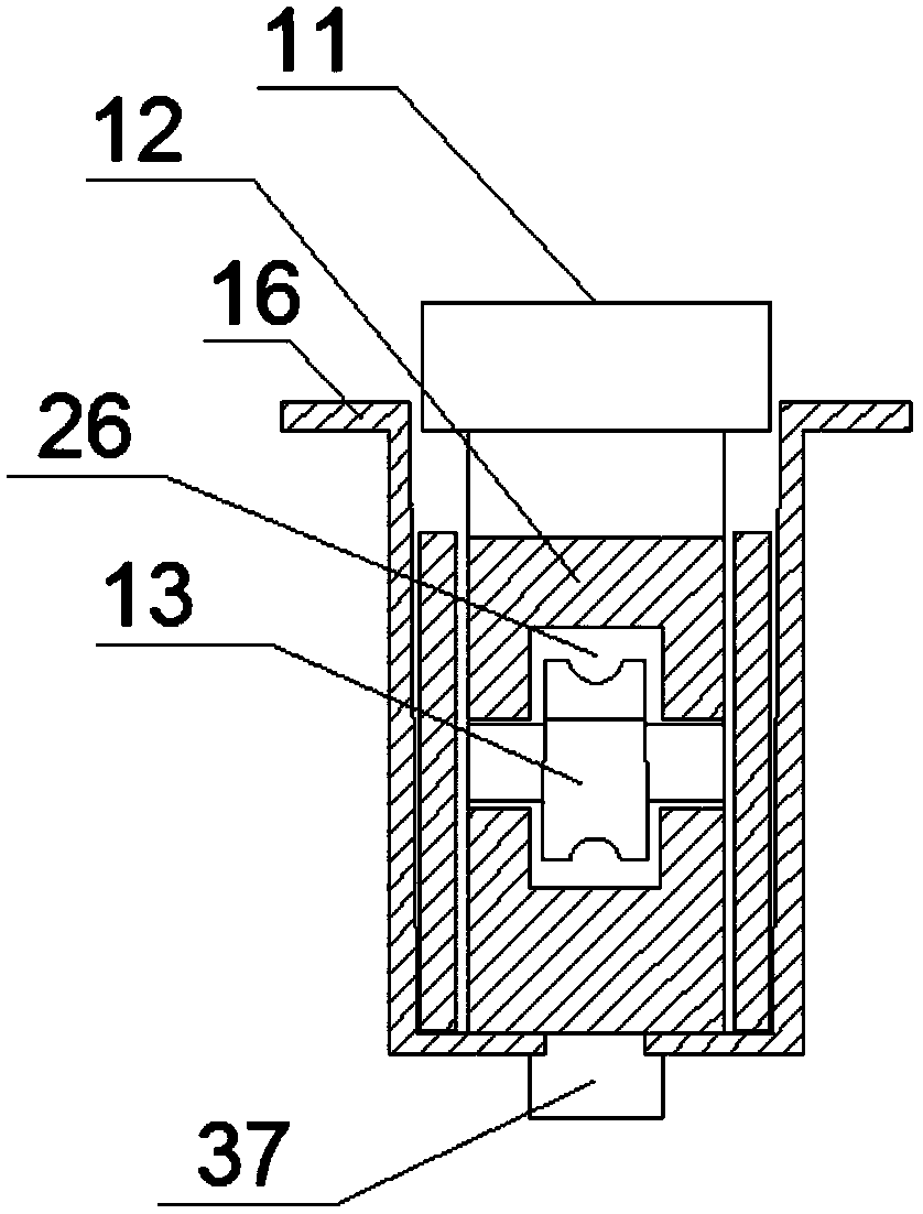
[0036] The invention provides a road energy collection device, see Figure 1-Figure 3 , including a plurality of pressure bodies 11, a plurality of support bodies 12, a pulley 13, a traction rope 14, a main body support frame 15, a casing 16, a hydraulic cylinder 18, a return spring 19, a support frame 20, a pressure frame 21, and a hydraulic energy storage Device 22, hydraulic motor 23, generator 24, fuel tank 25; the shape of the shell is a strip shell, the main body support frame is a strip shaped square frame, and the main body support frame is fixed in the shell; A plurality of said pressure bearing bodies and said supporting bodies are located in the main body supporting frame, respectively spaced from each other in the left and right directions of the main body supporting body frame, and adjacent pressure bearing bodies and supporting...
PUM
Abstract
The invention discloses a road energy harvesting device. The road energy harvesting device comprises pressure-bearing bodies, supporting bodies, pulleys, a traction rope, a body supporting frame, an outer shell, a hydraulic cylinder, a reset spring, a supporting frame, a pressure-bearing frame, a hydraulic energy storage device, a hydraulic motor, a generator and an oil tank. The body supporting frame is located in the outer shell. The pressure-bearing bodies and the supporting bodies are located in the body supporting frame in a spaced manner. Each supporting body is of a T-shaped structure, a groove is formed in the middle of each supporting body, and the corresponding pulleys are mounted in the grooves. The upper portion and the middle portion of each pressure-bearing body are each in a T shape, a groove is formed in the lower portion of each pressure-bearing body, and the corresponding pulleys are mounted in the grooves. A guide pulley is arranged on the supporting frame, and the hydraulic cylinder is fixed to the supporting frame and connected with the pressure-bearing frame. Guide wheels are arranged on the pressure-bearing frame. A piston rod is sleeved with the reset spring. One end of the traction rope is fixed to the body supporting frame, and the other end of the traction rope passes through the pulleys, the guide pulley and the guide wheels to be fixed to the supporting frame. The hydraulic cylinder, the hydraulic energy storage device, the hydraulic motor and the generator are connected in sequence, and the oil tank is connected with the hydraulic motor and the hydraulic cylinder. According to the device, hydraulic oil is not prone to leaking.
Description
technical field [0001] The invention relates to the field of energy collection devices, in particular to a road energy collection device. Background technique [0002] With the rapid development of human science and technology and the improvement of people's living standards, vehicles have become the main means of transportation for people to travel. The extension of roads and the popularity of vehicles have become a symbol of modern civilization. At the same time, in order to maintain the natural environment suitable for our survival, energy conservation and emission reduction and the exploration of green and renewable energy have become our primary goals. In recent years, people have studied a new way of energy collection, which is to recover and reuse the energy lost by vehicles through road deceleration devices. [0003] Patent No. CN1963197A discloses a road deceleration belt generating power device: the road deceleration belt generating power device belongs to power e...
Claims
Application Information
Patent Timeline
Application Date:The date an application was filed.
Publication Date:The date a patent or application was officially published.
First Publication Date:The earliest publication date of a patent with the same application number.
Issue Date:Publication date of the patent grant document.
PCT Entry Date:The Entry date of PCT National Phase.
Estimated Expiry Date:The statutory expiry date of a patent right according to the Patent Law, and it is the longest term of protection that the patent right can achieve without the termination of the patent right due to other reasons(Term extension factor has been taken into account ).
Invalid Date:Actual expiry date is based on effective date or publication date of legal transaction data of invalid patent.