Centrifugal fan blade, centrifugal fan and air conditioning device
A technology of centrifugal fan and centrifugal fan, which is applied in the field of centrifugal fan and air-conditioning equipment, and centrifugal fan, which can solve the problems of increasing the power consumption level of the motor load, reducing the efficiency of the centrifugal fan, and wasting materials, so as to reduce the cost and reduce the cost of the motor. Effects of load, prevention of secondary flow, reduction of noise and power consumption
- Summary
- Abstract
- Description
- Claims
- Application Information
AI Technical Summary
Problems solved by technology
Method used
Image

Examples
Embodiment 1
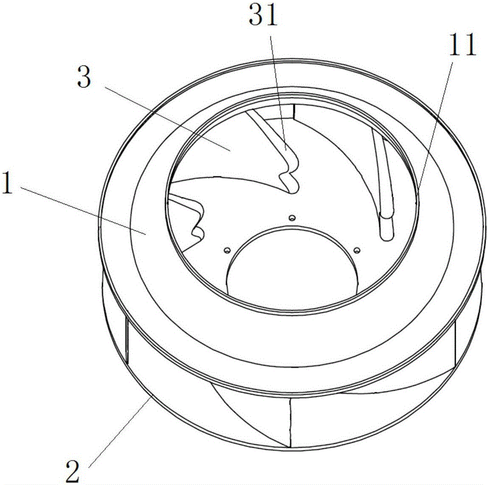
[0043] Such as figure 1 with figure 2 As shown, this embodiment provides a centrifugal fan blade, which includes a front disc 1, a rear disc 2 and a plurality of blades 3. Wherein, the front disk 1 is provided with an air inlet 11 for axially entering the airflow into the centrifugal blade. An air outlet is arranged between the rear disc 2 and the front disc 1 to allow the centrifugal blades to discharge air radially. A plurality of blades 3 are evenly arranged between the front disc 1 and the rear disc 2; wherein, the front edge 31 of the blade 3 is set in the shape of the outer edge of a bird's wing (such as Figure 1 to Figure 3 The shape of the leading edge 31 of the blade, and as Figure 4 to Figure 6 The leading edge curve shape shown).
[0044] In this embodiment, the centrifugal fan blade is driven by the motor to axially suck the airflow into the centrifugal fan blade from the air inlet 11, enter the flow channel through the front edge 31 of the blade 3, and then flow o...
Embodiment 2
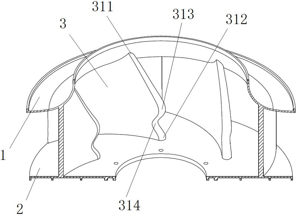
[0049] Preferably, as Figure 1 to Figure 3 As shown, this embodiment provides a centrifugal fan blade. Compared with the previous embodiment, the leading edge 31 of the blade 3 in this embodiment has a first end and a second end; the first end is close to the rear disc 2 The leading edge blade root 312, the second end is the leading edge blade tip 311 close to the front disc 1. Preferably, the leading edge blade root 312 in this embodiment is in contact with the plane of the inner bottom of the rear disc 2.
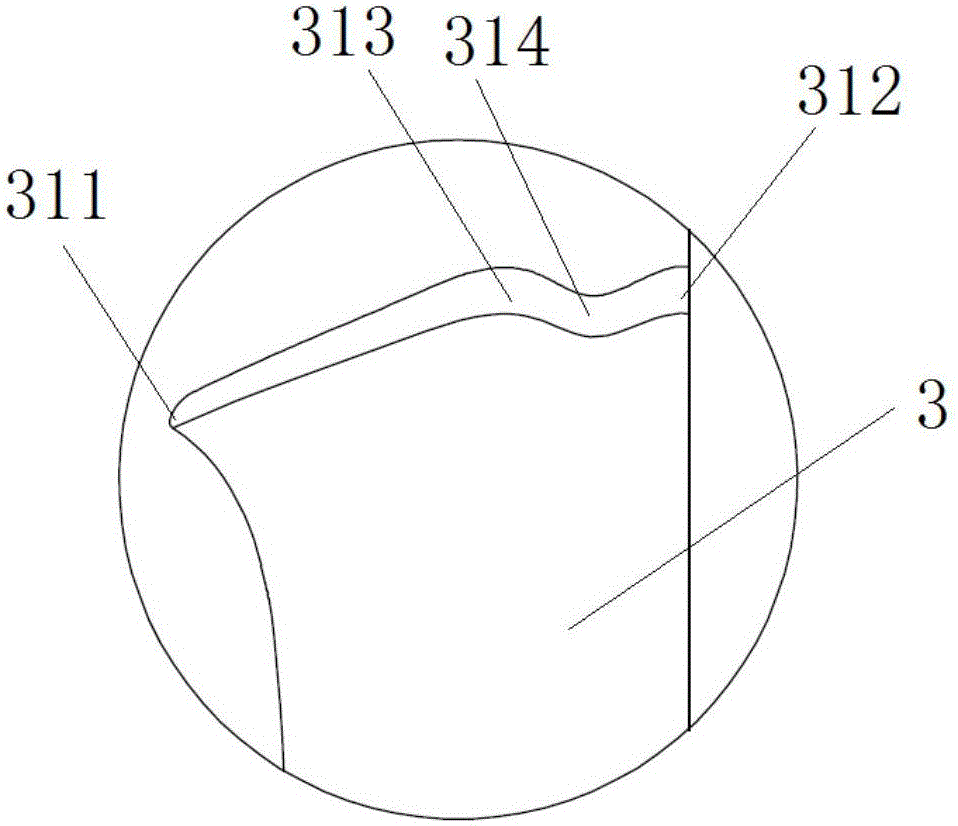
[0050] Wherein, the shape of the outer edge of the bird-like wing in this embodiment specifically refers to the curve shape change from the leading edge blade root 312 to the leading edge blade tip 311 sequentially showing concave and convex curves. The details are as follows: Figure 1 to Figure 6 As shown, in this embodiment, the front edge of the blade 3 is provided with protrusions 313 and recesses 314; wherein, the recesses 314 are located at the leading edge blade roo...
Embodiment 3
[0053] Preferably, this embodiment provides a centrifugal fan blade. Compared with the above embodiment, as Figure 1 to Figure 4 As shown, the concave portion 314 on the front edge of the blade in the centrifugal wind blade of this embodiment is located close to the front edge blade root 312. Correspondingly, the protrusion 313 and the recess 314 in this embodiment divide the leading edge of the blade into three sections with a smooth transition. Among them, the three sections of gentle transition include the first section from the leading edge tip 311 to the most convex part of the protrusion 313, and the second section from the most convex part of the protrusion 313 to the most concave part of the recess 314. , Gently transition from the deepest part of the recess 314 to the third section of the leading edge blade root 312. Among them, the third section in this embodiment is an arc-shaped structure that gently transitions from the deepest part of the recess 314 to the leadi...
PUM
 Abstract
Description
Claims
Application Information
 - R&D
- Intellectual Property
- Life Sciences
- Materials
- Tech Scout
- Unparalleled Data Quality
- Higher Quality Content
- 60% Fewer Hallucinations
Browse by: Latest US Patents, China's latest patents, Technical Efficacy Thesaurus, Application Domain, Technology Topic, Popular Technical Reports.
© 2025 PatSnap. All rights reserved.Legal|Privacy policy|Modern Slavery Act Transparency Statement|Sitemap|About US| Contact US: help@patsnap.com