Labyrinth-type magnetofluid sealing device

A magnetic fluid seal and labyrinth technology, applied in the direction of engine seals, bearing components, engine components, etc., can solve the problems of reduced sealing reliability, low secondary pressure bearing capacity, failure of magnetic fluid seals, etc., to improve secondary Pressure-bearing capacity, solving internal leakage problems, and improving the effect of magnetic field strength

Active Publication Date: 2016-10-12
GUANGXI UNIVERSITY OF TECHNOLOGY
View PDF6 Cites 7 Cited by
  • Summary
  • Abstract
  • Description
  • Claims
  • Application Information

AI Technical Summary

Problems solved by technology

[0002] When the external pressure of the ordinary magnetic fluid sealing device is greater than its rated pressure, the magnetic fluid seal will fail, and the leakage of the magnetic fluid will be large, resulting in weak self-repair ability, that is, the secondary pressure bearing capacity is low, thereby reducing the magnetic fluid. The reliability of the seal, so delaying the leakage of the magnetic fluid is of great significance for improving the pressure resistance and reliability of the magnetic fluid seal
Most of the existing sealing devices have a straight-through labyrinth seal structure when injecting magnetic fluid. Once leakage occurs, the leakage of the magnetic fluid will be large, which will lead to a decrease in the critical pressure resistance and self-repairing ability of the sealing device, and greatly reduce the sealing performance. reliability

Method used


Image

  • Labyrinth-type magnetofluid sealing device

Examples


Embodiment Construction

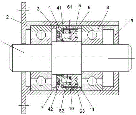
[0022] The present invention will be further described below in conjunction with accompanying drawing.

[0023] Such as figure 1 The shown labyrinth magnetic fluid sealing device includes shaft 1, housing 2, first pole shoe ring 4, second pole shoe ring 6, third pole shoe ring 5, permanent magnet I7, permanent magnet II10, permanent magnet III11, The shaft 1 is installed in the housing 2, the inner wall cross sections of the shaft 1 and the housing 2 are concentric circles, the first pole shoe ring 4 is installed on the inner wall of the housing 2, the first pole shoe ring The inner ring surface of 4 is close to the shaft 1, leaving a gap between it and the shaft 1;

[0024] The second pole shoe ring 6 is installed on the shaft 1 and is located on the right side of the first pole shoe ring 4; the third pole shoe ring 5 is installed on the inner wall of the housing 2 and is located on the first pole shoe ring 4 On the right side, the inner ring surface of the third pole shoe ...


PUM


Abstract

The invention relates to the field of machinery engineering sealing, and concretely relates to a labyrinth-type magnetofluid sealing device. The device comprises a shaft, a housing, a first pole shoe ring, a second pole shoe ring, and a third pole shoe ring; the first pole shoe ring is positioned at the left side of the second pole shoe ring, a pole tooth I is established at the right end of the first pole shoe ring, an annular groove I is established at the left end of the first pole shoe ring, a permanent magnet I is arranged in the annular groove I, a pole tooth II and a pole tooth III are established at the left end of the second pole shoe ring, an annular groove II is established at the right end of the second pole shoe ring, a permanent magnet III is arranged in the annular groove II, the third pole shoe ring is arranged at the external circular surface of the second pole shoe ring, a space is kept between the third pole shoe ring and the first pole shoe ring, a permanent magnet II is arranged in the space, the pole tooth II is positioned over the pole tooth I at the top of the first pole shoe ring, the pole tooth III is positioned below the pole tooth I at the bottom of the first pole shoe ring, and the pole tooth I stretches into the space composed of the pole tooth II and the pole tooth III.

Description

technical field [0001] The invention belongs to the technical field of mechanical engineering sealing, and in particular relates to a magnetic fluid sealing device with simple structure and high self-repairing ability. Background technique [0002] When the external pressure of the ordinary magnetic fluid sealing device is greater than its rated pressure, the magnetic fluid seal will fail, and the leakage of the magnetic fluid will be large, resulting in weak self-repair ability, that is, the secondary pressure bearing capacity is low, thereby reducing the magnetic fluid. Therefore, delaying the leakage of ferrofluid is of great significance for improving the pressure resistance and reliability of ferrofluid seals. Most of the existing sealing devices have a straight-through labyrinth seal structure when injecting magnetic fluid. Once leakage occurs, the leakage of the magnetic fluid will be large, which will lead to a decrease in the critical pressure resistance and self-re...

Claims


Application Information

Patent Timeline
Patent Type & Authority Applications(China)
IPC IPC(8): F16C33/80F16C33/82F16J15/43F16J15/447
CPCF16C33/80F16C33/82F16J15/43F16J15/4472
Inventor 杨小龙
Owner GUANGXI UNIVERSITY OF TECHNOLOGY
Why Eureka
Try Eureka